
Digital control oscillator and method, system and detector for hardware performance detection

A digitally controlled oscillation and hardware performance technology, applied in the electronic field, can solve the problems of high front-end and back-end requirements of chip design, long lock-up time, poor adaptability, etc.

Active Publication Date: 2013-09-25
日照金慧科技信息咨询有限公司
View PDF5 Cites 9 Cited by
  • Summary
  • Abstract
  • Description
  • Claims
  • Application Information

AI Technical Summary

Problems solved by technology

[0008] In order to solve the problems in the prior art that the length of the delay chain is indeterminate, resulting in poor adaptability, high requirements on the front and rear ends of the chip design, and long locking time, the embodiment of the present invention provides a digitally controlled oscillator, a hardware performance detection method, Systems and Detectors

Method used


Image

  • Digital control oscillator and method, system and detector for hardware performance detection
  • Digital control oscillator and method, system and detector for hardware performance detection
  • Digital control oscillator and method, system and detector for hardware performance detection

Examples


Embodiment 1

[0095] See image 3 As shown in , it shows a schematic structural diagram of the hardware performance detector provided by Embodiment 1 of the present invention. The hardware performance detector 30 may include, but is not limited to: a control unit 31 , a digitally controlled oscillator 32 , a first frequency divider 33 , a second frequency divider 34 , a first counter 35 and a second counter 36 .

[0096] The control unit 31 is connected with the digitally controlled oscillator 32 so as to control the digitally controlled oscillator 32 to output an oscillation clock, and the oscillation clock is the clock signal output by the digitally controlled oscillator 32 .

[0097] The first frequency divider 33 divides the frequency of a predetermined reference clock to obtain a first frequency-divided clock, and the second frequency divider 34 divides the frequency of the oscillation clock output by the digitally controlled oscillator 32 to obtain a second frequency-divided clock. I...

Embodiment 2

[0111] See Figure 4 As shown in FIG. 2 , it shows a schematic structural diagram of the digitally controlled oscillator in the hardware performance detector provided by Embodiment 2 of the present invention. The digitally controlled oscillator can be figure 1 The digitally controlled oscillator 32 shown in FIG. 2 may include: a NAND gate 410 , a first delay chain 420 , a second delay chain 430 and a NOT gate 440 .

[0112] The first delay chain 420 is formed by cascading at least two first delay units, such as Figure 4 As shown, the first delay chain 420 includes a plurality of cascaded first delay units such as the first delay unit 420a, the first delay unit 420b, and the first delay unit 420c. The first delay chain 420 may receive the first group selection signal sent by the control unit 31, and determine the effective first delay unit in the first delay chain 420 according to the first group selection signal. Wherein, the first group of selection signals is a group of ...

Embodiment 3

[0129] See Figure 5 As shown, it shows a method flow chart of the hardware performance detection method provided by Embodiment 3 of the present invention. The hardware performance detection method may include:

[0130] 501. After receiving an operation signal, receive a predefined parameter signal and a reference clock;

[0131] In a specific application scenario, the hardware performance detection method also includes a calibration process before step 501, and the predefined parameter signal can be obtained through the calibration process. The calibration process can include:

[0132] First, after receiving the calibration signal, receive the ratio signal and the reference clock;

[0133] Usually, the mode selection module 311 in the control unit 31 receives the calibration signal, indicating that the hardware performance detector 30 enters the calibration mode. In entering the calibration mode, the hardware performance detector 30 receives the ratio signal and the refer...


PUM


Abstract

The invention discloses a digital control oscillator, a method, system and detector for hardware performance detection and belongs to the technical field of electron. The detector for hardware performance detection comprises the digital control oscillator, a first frequency divider, a second frequency divider, a first counter, a second counter and a control unit. The control unit is connected with the digital control oscillator, so that the digital control oscillator is controlled to output an oscillation clock. Frequency division is conducted on a reference clock and the oscillation clock through the first frequency divider and the second frequency divider respectively so that a first frequency dividing clock and a second frequency dividing clock can be obtained. The first counter and the second counter count for the first frequency dividing clock and the second frequency dividing clock respectively in a preset counting period. A difference obtained through counting is output by the control unit. A parameter signal is determined under a correction mode; under an operation mode, the parameter signal is received and a detection value is output; voltage is reduced appropriately according to the detection value so that the power consumption can be reduced, or voltage is increased appropriately so that the stability of a circuit can be guaranteed.

Description

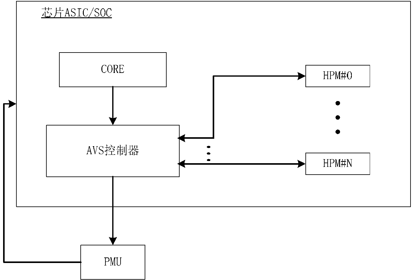
technical field [0001] The invention relates to the field of electronic technology, in particular to a digitally controlled oscillator, a hardware performance detection method, a system and a detector. Background technique [0002] AVS (Adaptive Voltage Scaling, adaptive voltage adjustment) technology, as an important method in chip low-power design, can automatically detect the operation of the current circuit, increase or decrease the power supply voltage of the chip, and realize the self-adaptive adjustment of the power supply voltage of the chip . A typical AVS system such as figure 1 As shown, the configuration core CORE configures the parameters of the AVS system through the bus, and starts the AVS controller; each HPM (Hardware Performance Monitor, hardware performance detector) detects the performance of the circuit in different areas, and returns the detection value to the AVS control The AVS controller decides whether to adjust the voltage according to the curren...

Claims


Application Information

Patent Timeline
Patent Type & Authority Applications(China)
IPC IPC(8): H03L7/099H03L7/08
Inventor 金鑫王新入谢谦
Owner 日照金慧科技信息咨询有限公司
Learn More