Copper electrolysis system and running method

A technology of copper electrolysis and electrolyte, applied in the field of copper electrolysis, can solve the problems of low production cost, low current density, high production cost, etc., and achieve the effects of improving circulation speed, reducing contact potential difference, and preventing concentration polarization

Active Publication Date: 2013-10-02
YANGGU XIANGGUANG COPPER
View PDF9 Cites 18 Cited by
  • Summary
  • Abstract
  • Description
  • Claims
  • Application Information

AI Technical Summary

Problems solved by technology

Therefore, the improvement of current density brings high production capacity to copper smelting enterprises, but also brings high power consumption troubles, which makes the existing copper smelting enterprises in two production situations: either low current density and low production capacity, and low production efficiency. The production cost, or adopt high current density and high capacity, bear high production cost

Method used


Image

  • Copper electrolysis system and running method
  • Copper electrolysis system and running method

Examples


Embodiment 1

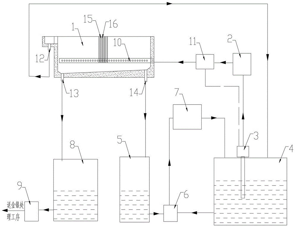
[0061] Place 54 thick copper anode plates and 53 pure copper cathode plates at intervals in the electrolytic cell, with Cu 2+ The concentration is 45g / l, and the concentration of free acid is 180g / l as the electrolyte. Start the frequency conversion pump to transport the electrolyte to the electrolytic cell through the electrolyte supply pipeline, and the electrolyte is supplied to it through the liquid supply device. It is sprayed in the direction close to the cathode plate, and then the sprayed electrolyte moves through the cavity between the plate and the side wall of the tank, and the cavity between the plate and the bottom of the tank to both ends of the tank, and finally from The overflow ports at both ends of the tank return to the electrolyte circulation system.

[0062] The process parameters of the electrolysis are as follows: the flow rate of the electrolyte is 110L / min, the pressure of the electrolyte is 0.3MPa, the temperature of the electrolysis is 58°C, and the ...

Embodiment 2

[0064] Place 54 thick copper anode plates and 53 pure copper cathode plates at intervals in the electrolytic cell, with Cu 2+ The concentration is 58g / l, and the concentration of free acid is 165g / l as the electrolyte. Start the frequency conversion pump to transport the electrolyte to the electrolytic cell through the electrolyte supply pipeline. The electrolyte is supplied to it through the liquid supply device. It is sprayed in the direction close to the cathode plate, and then the sprayed electrolyte moves through the cavity between the plate and the side wall of the tank, and the cavity between the plate and the bottom of the tank to both ends of the tank, and finally from The overflow ports at both ends of the tank return to the electrolyte circulation system.

[0065] The process parameters of electrolysis are as follows: the flow rate of electrolyte is 90L / min, the pressure of electrolyte is 0.25MPa, the temperature of electrolysis is 66°C, and the current density is 4...


PUM

PropertyMeasurementUnit
current efficiencyaaaaaaaaaa

Abstract

The invention provides a copper electrolysis system which comprises an electrolysis tank, a cooling device, a driving device, an electrolyte storage tank and a conducting bar, wherein a liquid supply device is arranged on an inside wall of the electrolysis tank; an outlet of the driving device is connected with an inlet of the cooling device; the outlet of the cooling device is connected with a liquid supply pipeline of the liquid supply device; an electrolyte draining port of the electrolysis tank is connected with the inlet of the electrolyte storage tank; the outlet of the electrolyte storage tank is connected with the inlet of the driving device; the conducting bar is arranged at an upper edge of the electrolysis tank; and a conductive rod of a cathode and a hanging lug of an anode are respectively lapped with the conducting bar. Due to the cooperative use of the electrolysis tank, the cooling device, the driving device and the conducting bar, the copper electrolysis system provided by the invention causes the current density to be higher and the electrolysis tank voltage to be lower during a copper electrolysis, so that the yield of copper is higher and the energy consumption is lower.

Description

technical field [0001] The invention relates to the technical field of copper electrolysis, in particular to a copper electrolysis system and an operation method. Background technique [0002] Electrolytic refining is the main method in the process of non-ferrous metal smelting, especially copper smelting. Among non-ferrous metals, the electrolysis or electrowinning processes of copper, lead, zinc and nickel are based on electrochemical principles. The process of copper electrolytic refining is as follows: the cathode and anode are placed in the electrolytic cell, and an electrochemical reaction occurs under the condition of electrification. Metal copper is continuously precipitated on the cathode to become cathode copper, and the anode is continuously dissolved, and copper enters the electrolyte in an ion state. [0003] With the rapid development of social economy, countries all over the world are expanding the scale of electrolytic copper production and transforming copp...

Claims


Application Information

Patent Timeline
Patent Type & Authority Applications(China)
IPC IPC(8): C25C1/12C25C7/00
CPCY02P10/20
Inventor 周松林王亚民杨家庭潘霞梁源王志普
Owner YANGGU XIANGGUANG COPPER
Why Eureka
Try Eureka