A control circuit for led AC drive

A technology for driving control circuits and control circuits, which is applied in the layout of electric lamp circuits, electric light sources, lighting devices, etc., can solve the problems of reducing the power efficiency of lamps, low power consumption of power supply circuits, insufficient power supply current, etc., and achieves low cost and circuit. High efficiency and small temperature rise of lamps

Inactive Publication Date: 2016-08-10
元烽 +1
View PDF3 Cites 0 Cited by
  • Summary
  • Abstract
  • Description
  • Claims
  • Application Information

AI Technical Summary

Problems solved by technology

Attached Figure 1~2 It is reasonable to provide starting power for the switching controller of the AC-DC switching power supply constant current drive circuit in the high-voltage power-taking mode shown, because after the controller is started, the output voltage of the auxiliary winding of the switching transformer will be greater than the output voltage of the Zener diode. Forcing the expansion transistor T to cut off, the power consumption of the power supply circuit is not high; and the disadvantages of using this kind of high-voltage power-taking method to supply power to the control circuit in the LED AC drive mode are very obvious: the efficiency is very low, the load capacity is very poor, and it can only Provide mA-level power supply current to the control circuit, otherwise the power consumed by the current-limiting resistors R3, R4 and the current expansion transistor T will be too large, which not only reduces the power supply efficiency of the lamp, but also increases the temperature rise of the lamp
For example, in figure 1 Among them, if the output voltage is 12V and the output current is 5mA, the current limiting resistor and the current expansion transistor will consume nearly 1.5W of power, and in the LED drive control circuit, the power supply current of 5mA is sometimes slightly insufficient

Method used


Image

  • A control circuit for led AC drive
  • A control circuit for led AC drive
  • A control circuit for led AC drive

Examples


Embodiment 1

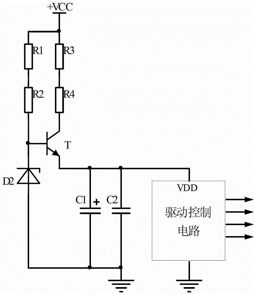
[0024] The structure diagram of the present invention is as Figure 4 As shown, the control circuit for LED AC drive of the present invention includes a power-taking circuit 1, a drive control circuit 2, an isolation circuit 3, and a filter / energy storage circuit 4, wherein the power-taking circuit 1 includes a first LED chip group 5, One pole of the isolation circuit 3 is connected to the positive pole of the first LED chipset 5, and the other pole is connected to the power supply terminal VDD of the drive control circuit 2; the filter / energy storage circuit 3 is connected in parallel to the power supply terminal VDD of the drive control circuit 2 and the common potential Between the reference point ground COM, the negative pole of the first LED chip group 5 is connected to the common potential reference point ground COM; the working power supply of the drive control circuit 2 is obtained by the forward voltage of the first LED chip group 5 through the isolation circuit 3 and ...

Embodiment 2

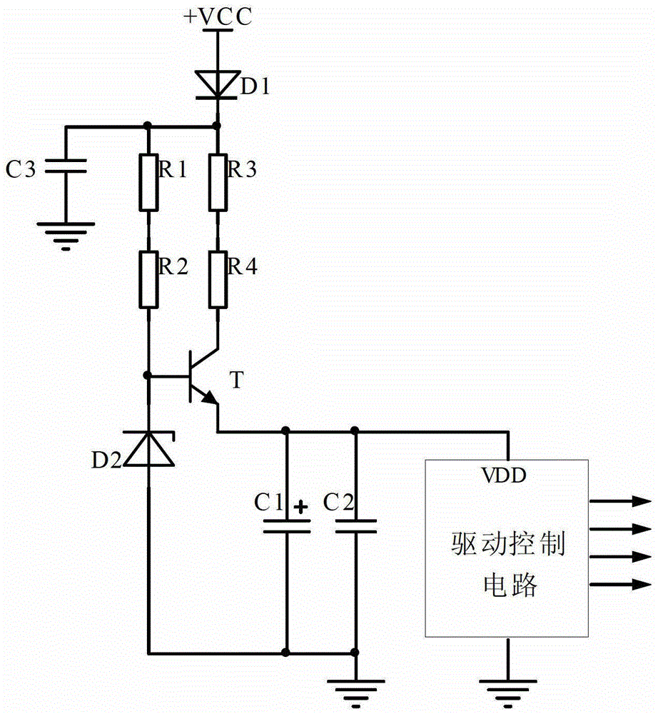
[0037] Figure 7It is the schematic diagram of the drive control circuit of the 30W non-electrolytic capacitor LED AC drive mode lamp. In this embodiment, the second LED chipset 6 includes several LED chips Di1, Di2, Di3, Di4...Dik, the first LED chipset 5 includes 3 LED chips D1, D2, D3 connected in series, the isolation circuit 3 is an isolation diode D, the working circuit of the first LED chipset 5 is 150mA, and the isolation diode D is a Schottky diode with low conduction voltage. The positive pole is connected to the positive pole of the first LED chipset 5, and the negative pole is connected to the power supply terminal VDD of the drive control circuit 2. The filter / energy storage circuit 4 is composed of three ceramic chip capacitors C1, C2, and C3 with a capacity of 22 μF and a withstand voltage of 16V. , the filter / energy storage capacitor C is connected in parallel between the power supply terminal VDD of the drive control circuit 2 and the common potential referenc...


PUM


Abstract

The invention relates to an LED alternating current drive control circuit, which comprises a power taking circuit, a drive control circuit, an isolation circuit and a filtering / energy storage circuit, wherein the power taking circuit comprises a first LED chip group, an electrode of the isolation circuit is connected with a positive electrode of the first LED chip group, and the other electrode of the isolation circuit is connected with a power end of the drive control circuit; the filtering / energy storage circuit is connected between the power end and a common potential point of the drive control circuit in parallel, and a negative electrode of the first LED chip group is connected to the common potential reference point; and a working power supply of the drive control circuit is provided by forward voltage of the first LED chip group after passing through the isolation circuit and the filtering / energy storage circuit. The power taking circuit further comprises a second LED chip group, and the isolation circuit is connected between the first LED chip group and the second LED chip group. The LED alternating current drive control circuit has the advantages of simple circuit, small number of components, low cost and high reliability. The LED alternating current drive control circuit provided by the invention is high in efficiency and small in lamp temperature rise.

Description

technical field [0001] The invention is an LED AC drive control circuit suitable for various LED lighting fixtures working in an AC drive mode, and belongs to the innovative technology of the LED AC drive control circuit. Background technique [0002] LED light source has the advantages of environmental protection, energy saving, long service life, etc., and is considered to be one of the most promising lighting sources in the 21st century, especially suitable for offices, classrooms, shopping malls, parking lots, waiting rooms, subways, tunnels, roads, etc. Public places illuminated by time. [0003] In LED lighting fixtures, although the isolation AC-DC switching power supply constant current drive method solves the safety problem, its disadvantages are large drive current, complex drive circuit, poor reliability, high cost, low efficiency, and large size. ; In addition, one or more electrolytic capacitors are used in the switching power supply, so that the life of the dr...

Claims


Application Information

Patent Timeline
Patent Type & Authority Patents(China)
IPC IPC(8): H05B37/02
Inventor 潘永雄元烽
Owner 元烽
Why Eureka
Try Eureka