Swing stirring device for preparing semisolid slurry and rheoforming equipment

A technology of semi-solid slurry and stirring device, which is applied in chemical instruments and methods, mixers, shaking/oscillating/vibrating mixers, etc., to achieve the effects of simple equipment structure, reduced preparation costs, and reduced difficulty

Inactive Publication Date: 2013-10-09
UNIV OF SCI & TECH BEIJING
View PDF14 Cites 10 Cited by
  • Summary
  • Abstract
  • Description
  • Claims
  • Application Information

AI Technical Summary

Problems solved by technology

In the equipment of the above technologies, there is no special swing stirring device for preparing semi-solid slurries of light alloy

Method used


Image

  • Swing stirring device for preparing semisolid slurry and rheoforming equipment
  • Swing stirring device for preparing semisolid slurry and rheoforming equipment
  • Swing stirring device for preparing semisolid slurry and rheoforming equipment

Examples


example 1

[0025] (1) The liquidus line of the ZL101A aluminum alloy used in the test is 615°C. Melt the alloy in a crucible resistance furnace. When the temperature of the alloy reaches about 720°C, use a bell jar to press the dried hexachloroethane into the melt The lower part (the addition amount is 0.5% of the total weight of the alloy liquid) is gently shaken to carry out the degassing and slag removal refining treatment of the alloy melt, and finally the temperature of the alloy melt is lowered to 630°C for heat preservation.

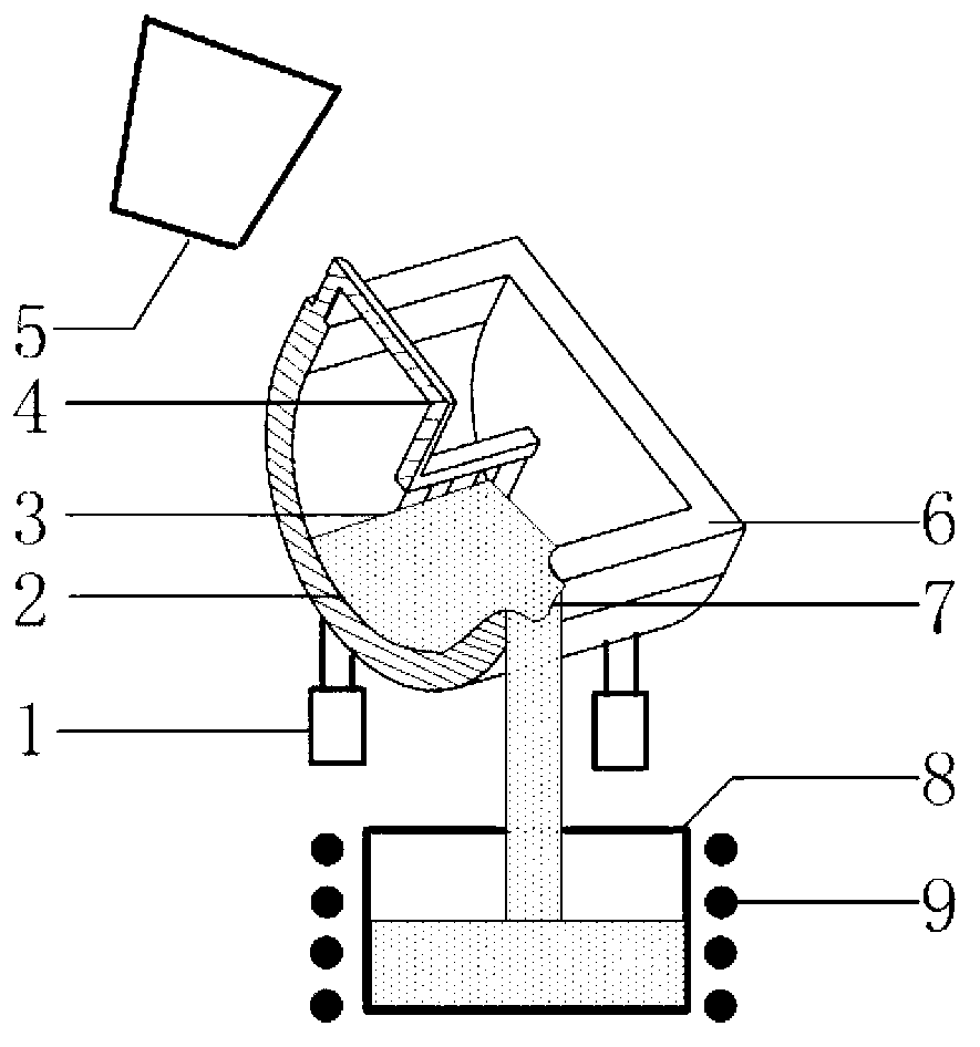
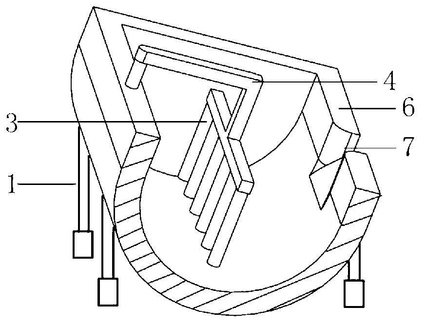
[0026] (2) Set the temperature of the mixing chamber and stirring rod of the swing stirring device of the device of the present invention to 200°C, and the swing frequency to 30 times / minute, and pour the alloy melt smelted in the previous step into the swing stirring device with a ladle 5 In the stirring chamber 6, driven by the swing power device, the stirring chamber 6 is swayed by the swinging lifting rod 1 on both sides, and the swaying of the stirring c...

example 2

[0028] (1) The liquidus temperature of the A356 aluminum alloy used in the test is 615°C. The aluminum alloy ingot is put into a crucible resistance furnace with a preheating temperature of 400°C. After the temperature of the alloy liquid reaches 700°C, it is refined. Press the dried hexachloroethane into the lower part of the melt (the amount added is 0.5% of the total weight of the alloy liquid), and shake it gently to degas the alloy melt, remove slag and refine it, and finally melt the alloy Body temperature drops to 640°C for heat preservation.

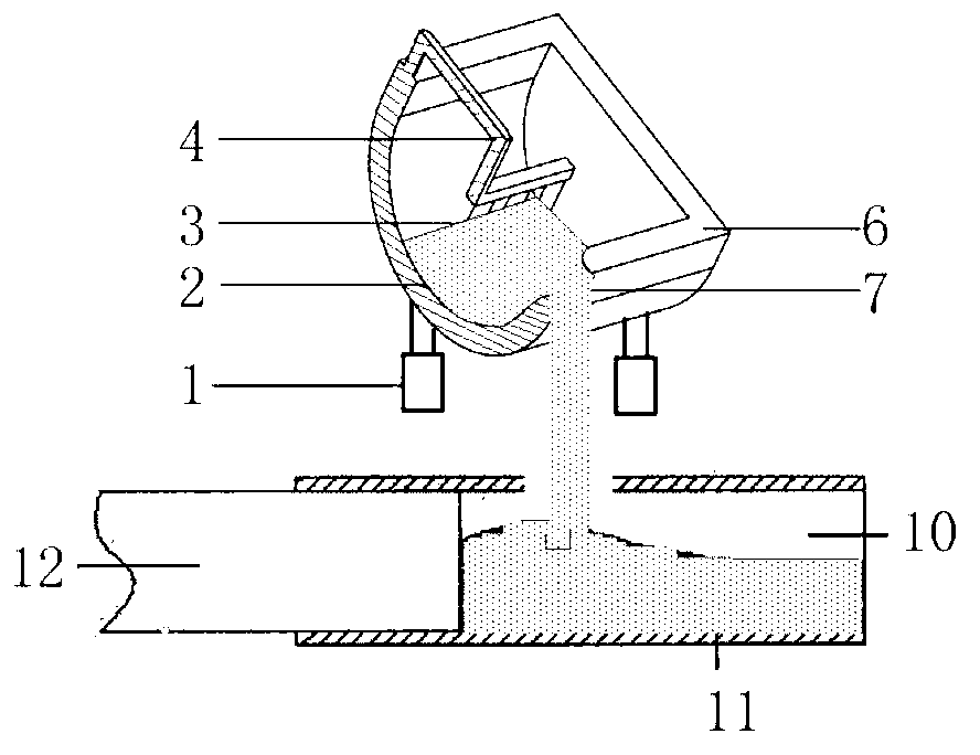
[0029] (2) Set the temperature of the stirring chamber and the stirring rod of the swing stirring device of the device of the present invention to 250°C, and the swing frequency is 60 times / minute, and pour the alloy melt 2 smelted in the previous step into the stirring chamber of the swing stirring device 6, the superheated metal is cooled by the wall and the fixed stirring rod 3, and at the same time, under the action of swing,...


PUM

PropertyMeasurementUnit
Heightaaaaaaaaaa
Thicknessaaaaaaaaaa

Abstract

The invention provides a swing stirring device for preparing semisolid slurry and rheoforming equipment, and belongs to the field of semisolid metal processing technology. The swing stirring device for preparing the semisolid slurry is composed of swing lifting rods, a swing power device, an alloy melt, fixed stirring rods, a supporting frame, a pony ladle, a stirring chamber, a small sprue, a crucible, heating elements, a die-casting machine, a pressing chamber of the die-casting machine, the semisolid slurry, an injection punch, an extruding machine, a pressing chamber of the extruding machine, an extruding punch and the like. Based on the principles of cooling and stirring, the alloy melt flows in the stirring chamber under the action of the swing stirring rods, the nucleation of the alloy melt is promoted to prepare the semisolid slurry under the stirring action of the fixed stirring rods, and the rheoforming equipment achieves rheoforming easily when matched with forming equipment, such as the die-casting machine, the extruding machine or a forging machine. The swing stirring device for preparing the semisolid slurry and the rheoforming equipment are simple in structure, small in investment, low in production cost, stable and reliable in continuous preparation work, and quite suitable for preparation and forming production of the semisolid metal slurry or blank.

Description

technical field [0001] The invention belongs to the technical field of semi-solid metal processing, and in particular provides a swing stirring device for preparing semi-solid slurry and rheological deformation equipment. Background technique [0002] Since the early 1970s, researchers such as M C Flemings of the Massachusetts Institute of Technology created the concept of metal semi-solid forming, and the preparation and forming technology of semi-solid metal paste has attracted widespread attention from all over the world as a new technology. According to the literature "Behavior of metal alloys in the semisolid state" (M C Flemings, Metall Trans, 1991, 22A: 957-981), "a suspension cone type semi-solid metal slurry preparation and delivery device" (Kang Yonglin, China Patent, 200810114097.3, 2008) and "Semi-solid Processing Theory and Technology of Metal Materials" (monograph: Kang Yonglin, Mao Weimin, Hu Zhuangqi, Science Press, 2004) reported that there are many methods ...

Claims


Application Information

Patent Timeline
IPC IPC(8): B22D17/30B21C33/00B01F11/00
Inventor 康永林周冰朱国明祁明凡张欢欢
Owner UNIV OF SCI & TECH BEIJING
Why Eureka
Try Eureka