Vapor deposition method

A vapor deposition and deposition chamber technology, applied in the field of vacuum chemical vapor deposition systems, can solve problems such as large density difference, difficulty in uniform deposition of large materials, inconsistent quality of different parts, etc., to ensure consistency and solve difficulties in chemical deposition production and manufacturing Effect

Inactive Publication Date: 2013-10-09
ADVANCED FOR MATERIALS & EQUIP
View PDF5 Cites 7 Cited by
  • Summary
  • Abstract
  • Description
  • Claims
  • Application Information

AI Technical Summary

Problems solved by technology

[0005] Deposition uniformity is a very important quality indicator of chemical vapor deposition, but since there is no chemical vapor deposition system suitable for large-scale chemical vapor deposition, it is necessary to ensure the deposition of large materials (especially materials with large heights) or products Uniformity is very difficult, which hinders the development of many scientific fields such as aerospace, aviation, transportation, and civilian technology.
[0006] The chemical vapor deposition furnace or deposition system developed through the transformation and development of the traditional vacuum furnace, because there is only one deposition gas path and a single heating temperature zone, it is difficult to ensure that the carbon-carbon composite material obtained by deposition can be uniformly deposited and uniformly heated
Due to the single deposition gas path, hydrocarbon gas rushes into a certain part of the deposition chamber at a certain flow rate and velocity, and pyrolyzes in an instant to form matrix carbon deposited inside or on the surface of the bad material. The defects that exist are along the The concentration of hydrocarbon gas and the deposition reaction in the height direction of the deposition chamber gradually weaken from bottom to top. Obviously, the larger the furnace load, the greater the difference in the concentration of hydrocarbon gas in all directions of the deposition chamber, resulting in products at different positions or at the same time. The density of different parts of a product varies greatly, resulting in inconsistent quality of the same product or inconsistent quality of different parts of the same product

Method used


Image

  • Vapor deposition method
  • Vapor deposition method

Examples


Embodiment Construction

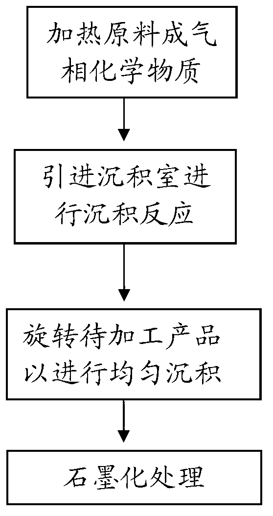
[0028] The invention discloses a gas phase deposition method to ensure the deposition uniformity of the final product and the consistency of product quality.

[0029] The following will clearly and completely describe the technical solutions in the embodiments of the present invention with reference to the accompanying drawings in the embodiments of the present invention. Obviously, the described embodiments are only some, not all, embodiments of the present invention. Based on the embodiments of the present invention, all other embodiments obtained by persons of ordinary skill in the art without making creative efforts belong to the protection scope of the present invention.

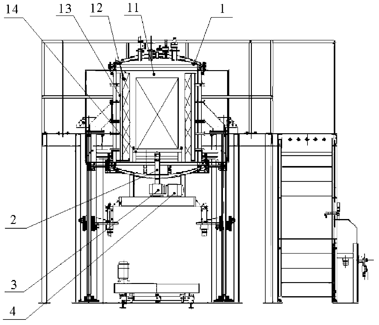
[0030] see figure 1 and figure 2 , figure 1 A schematic flow chart of the vapor deposition method provided by the embodiment of the present invention, figure 2 A schematic structural diagram of a vapor deposition furnace provided in an embodiment of the present invention.

[0031] The vapor deposi...


PUM


Abstract

The invention discloses a vapor deposition method comprising the following steps of: heating raw materials until the raw materials become a vapor chemical substance, wherein the raw materials participate in deposition reaction; introducing the vapor chemical substance to a deposition chamber with products to be processed to carry out deposition reaction; and rotating the products to be processed in the deposition chamber. Known from the technical scheme, the vapor deposition method provided by the embodiment of the invention has the advantages that the products to be processed in the deposition chamber are rotated when subjected to vapor deposition, then, gas in the deposition chamber is stirred to a certain extent, and the products are subjected to vapor deposition while being rotated in the deposition chamber, so that the deposition uniformity of the final products is favorably achieved, and the quality consistency of the products is ensured. Therefore, by using the vapor deposition method, a vapor deposition finished product which is uniform in material can be obtained, and the problem that the chemical deposition production of the current large carbon-carbon composite material is difficult is effectively solved.

Description

technical field [0001] The invention relates to the field of vacuum chemical vapor deposition systems, in particular to a vapor deposition method. Background technique [0002] Chemical vapor deposition is a process widely used in the production of new materials, such as composite materials such as C / C, C / SiC or SiC / SiC. With the development of society and the advancement of technology, aerospace, aviation, transportation and many other fields have higher requirements for chemical vapor deposition materials, and the size of materials or products is becoming larger. [0003] Chemical vapor deposition is to use the principle of chemical vapor deposition to heat the substances participating in the chemical reaction to a certain process temperature, and under the action of the traction force generated by the vacuum pump pumping system, lead them to the deposition chamber for reaction, deposition, and formation of new solid substances. process. In order to obtain the deposition...

Claims


Application Information

Patent Timeline
Patent Type & Authority Applications(China)
IPC IPC(8): C23C16/458C23C16/26C23C16/32
Inventor 戴煜胡祥龙
Owner ADVANCED FOR MATERIALS & EQUIP
Why Eureka
Try Eureka