High resolution stereo mapping and reconnaissance integrated camera optical system

A high-resolution, optical system technology, which is applied in the field of detection integrated camera optical imaging system, can solve the problems such as mirror processing, detection and assembly cannot be adopted, large field of view cannot be realized, and mirror processing is difficult, etc. Achieve the effect of low distortion, reduced quantity and simple composition

Active Publication Date: 2013-10-09
北京航天创智科技有限公司
View PDF4 Cites 16 Cited by
  • Summary
  • Abstract
  • Description
  • Claims
  • Application Information

AI Technical Summary

Problems solved by technology

[0004] The United States is a powerful country in aerospace remote sensing and occupies a dominant position in the field of space exploration. The high-resolution visible light imaging reconnaissance cameras in the United States mainly include KH-11, KH-12, Geoeye-1 and WorldView II. Three-dimensional surveying and mapping of the surface is carried out by orbital stereoscopic imaging. The disadvantage is that only a specific area can be surveyed and mapped in one orbit, and the observation range is limited.
The optical system of the high-resolution visible light CCD camera mainly adopts two structural types, namely the coaxial reflective three-mirror anastigmatism system TMA and the off-axis TMA system. Under the same focal length, aperture and field of view, the coaxial TMA has the volume The advantages of small size and light weight, but can not achieve a large field of view, large distortion; off-axis TMA often makes the processing of the mirror extremely difficult, and traditional methods cannot be used for mirror processing, inspection and assembly, and its outstanding disadvantage is the volume and weight Big

Method used


Image

  • High resolution stereo mapping and reconnaissance integrated camera optical system
  • High resolution stereo mapping and reconnaissance integrated camera optical system

Examples


Embodiment Construction

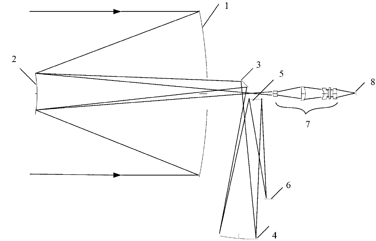
[0023] Such as figure 1 As shown, the optical system of the present invention includes two or three camera optical systems; when it is two camera optical systems, the content of the shooting is front view and front view; when it is three camera optical systems, the shooting content is front view, Front view and rear view; each camera optical system adopts a common optical path structure, and the camera optical system is of the same type. Each group of camera optical system consists of primary mirror 1, secondary mirror 2, plane mirror 3, three mirrors 4, four mirrors 5, high-resolution stereo detection branch focal plane receiving device 6, laser ranging branch relay lens group 7 and the focal plane device 8 of the laser ranging branch.

[0024] Further description is carried out below by specific embodiment:

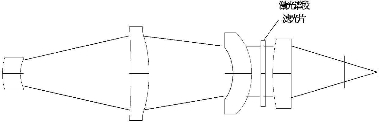
[0025] The working spectrum of the high-resolution stereo detection branch of the camera optical system is 0.45μm-0.9μm, and the working spectrum of the laser ranging...


PUM


Abstract

A high resolution stereo mapping and reconnaissance integrated camera optical system comprises a high resolution stereo detection branch and a laser ranging branch, wherein the high resolution stereo detection branch and the laser ranging branch adopt a shared primary mirror and a shared secondary mirror, adopt independent subsequent optical paths and independent optical elements, and form two independent optical branches. The two branches are different in field angles of incident light rays, a field out of an axis is utilized by the high resolution stereo detection branch, a field on the axis is utilized by the laser ranging branch, the light rays in the field of the two branches simultaneously reach the primary mirror and the secondary mirror, a light beam of the high resolution stereo detection branch passes though four aspheric surface reflecting mirrors and then reach a high resolution stereo detection focal plane to be imaged, and a light beam of the laser ranging branch passes through the primary mirror and the secondary mirror, then passes through an optical filter and laser relay lens set and then is converged on a laser focal plane. The high resolution stereo mapping and reconnaissance integrated camera optical system has the advantages that resolution is high, distortion is zero, an optical-mechanical structure is high in integration level, the size is small and the weight is light. The high resolution stereo mapping and reconnaissance integrated camera optical system achieves high resolution, high precision detection and stereo ranging mapping functions for large-range surface features.

Description

technical field [0001] The invention belongs to the technical field of space optical remote sensors, and relates to a method for realizing a detection integrated camera optical imaging system suitable for high-resolution cameras in the visible light and near-infrared bands and laser ranging. Background technique [0002] Aerospace remote sensing reconnaissance and surveying and mapping technology is an important part of aerospace earth observation and imaging technology, and also an important part of military aerospace combat support system. An important part of the support system has developed into an important part of the combat capability of modern warfare; at the same time, it is also a modern and efficient surveying and mapping technology in the field of civilian surveying and mapping technology. [0003] Aerospace earth observation payloads mainly include: visible light CCD cameras, infrared cameras, synthetic aperture radars, and some satellite platforms are equipped ...

Claims


Application Information

Patent Timeline
Patent Type & Authority Applications(China)
IPC IPC(8): G02B27/00G02B17/08G02B5/10G02B1/00G01C11/02
Inventor 汤天瑾
Owner 北京航天创智科技有限公司
Why Eureka
Try Eureka