
A lightning protection overvoltage protection device

A technology of overvoltage protection devices and varistors, applied in the direction of emergency protection circuit devices for limiting overcurrent/overvoltage, emergency protection circuit devices, electrical components, etc., can solve the problem of rated operating current limitation and increased probability of damage , Reduce the probability of power frequency overvoltage deflagration accidents of pressure sensitive components, etc.

Inactive Publication Date: 2016-03-30
SOUTH CHINA UNIV OF TECH +2
View PDF10 Cites 3 Cited by
  • Summary
  • Abstract
  • Description
  • Claims
  • Application Information

AI Technical Summary

Problems solved by technology

Used in series with the gap, it can prevent the ZnO varistor from aging and failure, but it will increase the breakdown initiation voltage of the line. When the operating overvoltage (power frequency overvoltage) amplitude does not reach the breakdown voltage (ZnO component breakdown voltage When the sum of gap breakdown voltages), no current flows through the components and cannot protect the circuit
[0008] To sum up, in order to reduce the probability of power frequency overvoltage deflagration accidents of varistors, the varistor voltage of varistors can be increased, but this will inevitably increase the pulse residual voltage, and the protected line will be damaged by operating overvoltage and fault power frequency overvoltage The probability of the accident is greatly increased; the three-terminal device combined with the PTC thermal element and the ZnO varistor can reduce the probability of the power frequency overvoltage deflagration accident of the varistor, and can achieve a lower pulse residual voltage at the same time, but the rated work of the protected circuit The current is limited; the application of ZnO varistors in series with the gap can prevent deflagration accidents caused by long-term load aging of varistors, but the protection ability against circuit operation overvoltage and fault power frequency overvoltage is reduced

Method used


Image

  • A lightning protection overvoltage protection device
  • A lightning protection overvoltage protection device
  • A lightning protection overvoltage protection device

Examples


Embodiment 1

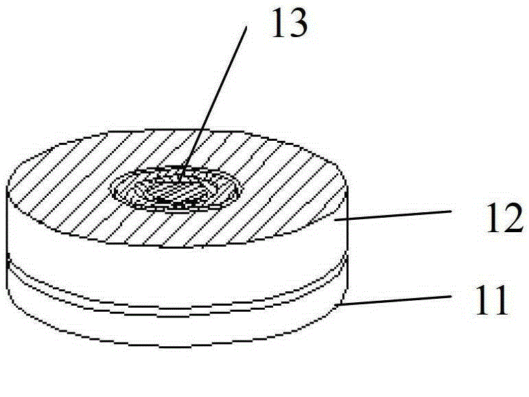
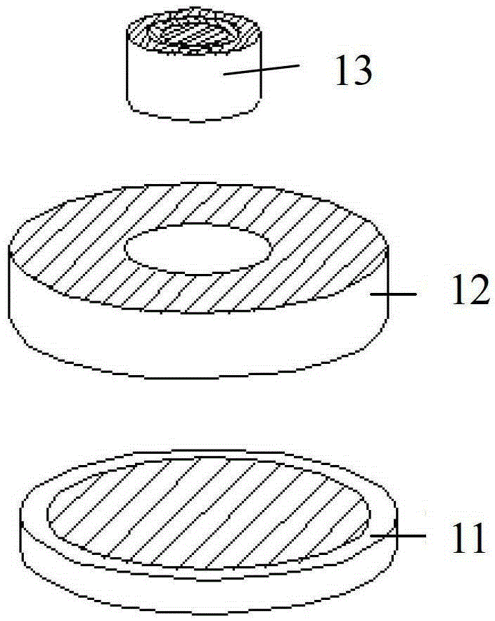
[0037] Such as Figure 1~2As shown, the lightning and overvoltage protection device of the present embodiment includes a zinc oxide varistor 11, a positive temperature coefficient ceramic thermistor 12 and a gas discharge tube 13, and the positive temperature coefficient ceramic thermistor 12 is made In a ring structure, the size of the inner hole of the positive temperature coefficient ceramic thermistor sheet 12 matches the outer diameter of the gas discharge tube 13, and the gap between the two is 0.1 to 1mm; the thickness of the positive temperature coefficient ceramic thermistor sheet 12 is the same as The gas discharge tube 13 has the same height, and the outer diameters of the zinc oxide varistor sheet 11 and the positive temperature coefficient ceramic thermistor sheet 12 are consistent; The upper electrode surface of the gas discharge tube 13 is placed in the inner hole of the positive temperature coefficient ceramic thermistor sheet 12 by soldering, and the lower end...

Embodiment 2

[0047] Such as Figure 5-6 As shown, the lightning protection overvoltage protection device of the present embodiment includes a zinc oxide varistor 21, a positive temperature coefficient ceramic thermistor 22 and a gas discharge tube 23, a zinc oxide varistor 21, a positive temperature coefficient thermal The varistor sheets 22 are all square, and the external dimensions of the varistor sheets, thermistor sheets and gas discharge tubes need to be properly matched: the gas discharge tube specifications adopted are the same as in Embodiment 1, and the size of the varistor sheets used is long* Width*height=15*15*3mm, the dimensions of the thermistor used are length*width*height=15*9*5mm. The lower electrode surface of the positive temperature coefficient thermistor sheet 22 is welded to the upper electrode surface of the zinc oxide varistor sheet 21 by soldering; the gas discharge tube 23 is located on one side of the zinc oxide varistor sheet 21, and its lower end surface is co...

Embodiment 3

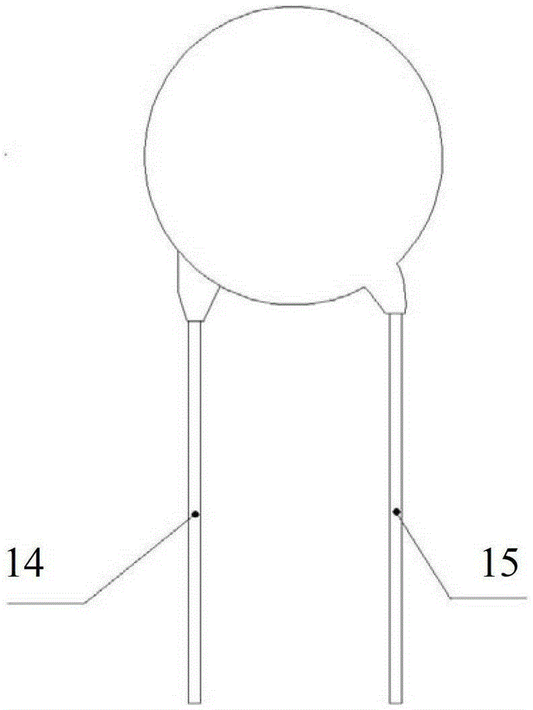
[0050] The lightning and overvoltage protection device of this embodiment includes a piezoresistor 31 , a positive temperature coefficient thermistor 32 and a gas discharge tube 33 . Such as Figure 9 As shown, the electrode on one side of the positive temperature coefficient thermistor sheet 32 ​​is welded with a lead wire, which is the lead end 34; the electrode on the other side of the positive temperature coefficient ceramic thermistor sheet 32 ​​and the electrode on one side of the piezoresistor sheet 31 are welded together by soldering, The common terminal is formed as the lead-out terminal 36 at the same time; The varistor sheet 31 and the positive temperature coefficient thermistor sheet 32 ​​are encapsulated with epoxy resin and cured to form a package body, and the two ends of the gas discharge tube are respectively connected to the lead-out end 34 and the lead-out end 36 to form the lightning protection device of this embodiment. When using the overvoltage protecti...


PUM


Abstract

The invention discloses an anti-thunder overvoltage protection device. The anti-thunder overvoltage protection device comprises a piezoresistor, a positive temperature coefficient thermistor and a gas discharge tube, wherein the positive temperature coefficient thermistor is connected with the gas discharge tube in parallel and then connected with the piezoresistor in series; the positive temperature coefficient thermistor and the piezoresistor form a thermal coupling relationship. The piezoresistor, the positive temperature coefficient thermistor and the gas discharge tube can be packaged into a whole, or the piezoresistor and the positive temperature coefficient thermistor are packaged into a whole, thus a packaged body is formed, and the gas discharge tube is located outside the packaged body. The anti-thunder overvoltage protection device not only can restrain operation overvoltage and fault power frequency overvoltage, but also can have the protection function of a normal voltage-sensitive element when lightning stroke pulse overvoltage occurs.

Description

technical field [0001] The invention relates to lightning protection and overvoltage protection technology, in particular to a composite lightning protection and overvoltage protection device. Background technique [0002] ZnO varistors have been widely used in power electronic circuits to absorb overvoltage caused by lightning pulses and power frequency overvoltage caused by system operation and system failure. However, the varistor itself has a certain limit for absorbing surge energy. The varistor connected in parallel to the power circuit absorbs overvoltage energy (especially the long-lasting power frequency overvoltage). At the same time, its own temperature rises. When the varistor When the energy absorbed by the resistance is too large, the varistor may explode and catch fire. Nowadays, this problem is usually solved by increasing the varistor voltage and diameter of the varistor, but this reduces the absorption wave of the varistor to a certain extent. The protecti...

Claims


Application Information

Patent Timeline
Patent Type & Authority Patents(China)
IPC IPC(8): H02H9/04
Inventor 卢振亚陈奕创沈朝阳杨凤金
Owner SOUTH CHINA UNIV OF TECH
Learn More