Method and apparatus for measuring sky brightness distribution based on full-automatic spectrum beam-splitting scanning

A brightness distribution, fully automatic technology, used in spectrum surveys, photometry using electrical radiation detectors, etc., can solve problems such as photo errors, image brightness measurement limitations, ultraviolet radiation response errors, etc., to ensure accuracy and avoid errors. Effect

Inactive Publication Date: 2013-10-16
CHINA ACAD OF BUILDING RES +1
View PDF3 Cites 3 Cited by
  • Summary
  • Abstract
  • Description
  • Claims
  • Application Information

AI Technical Summary

Problems solved by technology

[0014] 2. There is an error in the response to infrared radiation
[0015] The spectral range of luminance measurement is the visible light region. An ideal detector should not respond to infrared radiation. However, some photodetectors, such as silicon photodiodes, have strong responsivity in the near-infrared region. If the added V(λ ) to correct the cut-off of the filter for infrared radiation is not zero, which will cause significant errors
[0016] 3. There is an error in the response to ultraviolet radiation
[0017] Luminance measurement also cannot respond to radiation in the ultraviolet region, and the photomultiplier tubes and silicon photodiodes used in the luminance meter have varying degrees of response in the ultraviolet region, which will also cause certain errors
[0018] 4. The nonlinear error of the detector
[0020] 5. Temperature error
[0024] 1. Error caused by photo quality
[0025] This technology mainly uses digital image processing for measurement, so it has high requirements for photo quality, and the quality of photos has a lot to do with parameters such as optical lens and exposure time. Due to t...

Method used


Image

  • Method and apparatus for measuring sky brightness distribution based on full-automatic spectrum beam-splitting scanning
  • Method and apparatus for measuring sky brightness distribution based on full-automatic spectrum beam-splitting scanning
  • Method and apparatus for measuring sky brightness distribution based on full-automatic spectrum beam-splitting scanning

Examples


Embodiment Construction

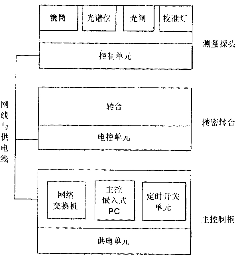
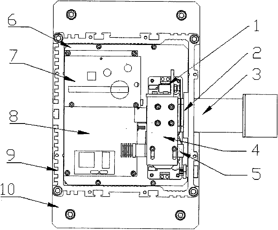
[0066] Such as figure 2 As shown, the sky scanning luminance meter device is mainly composed of three parts: the measuring probe part, the precision turntable, and the main control cabinet. The measuring probe part is mainly composed of steering gear 1, optical shutter 2, lens barrel 3, connecting plate 4, calibration lamp 5, spectrometer 6, Ethernet switch 7, control circuit 8 and housing 9, such as image 3 , 4 , 5 shown. The most important part is the spectrometer, which is used to measure the sky light by means of spectral scanning, and is fixed on the shell by screws. The built-in temperature sensor of the spectrometer can detect the temperature change of the spectrometer at any time, and make temperature correction in time. The calibration lamp uses a 2856K tungsten lamp, driven by constant current, and emits uniform light through the integrating sphere. The inner diameter of the integrating sphere is 36mm. The steering gear can control the light gate, close the lig...


PUM

PropertyMeasurementUnit
Brightnessaaaaaaaaaa
Diameteraaaaaaaaaa

Abstract

The invention relates to an apparatus for measuring sky brightness distribution based on full-automatic spectrum beam-splitting scanning. The apparatus is characterized in that the apparatus comprises a measuring probe portion, a precise rotary table, and a main control cabinet. The measuring probe portion consists of a lens cone, a calibration lamp, an optical shutter, a spectrograph, a temperature sensor, a control circuit and a thermally-insulated cover; the spectrograph is used for measuring skylights; and the temperature sensor is arranged inside the spectrograph so as to detect the temperature changing of the spectrograph at any time. The precise rotary table includes a driving control circuit and a rotary table body; the measuring probe portion is installed at the precise rotary table; and the driving control circuit drives the rotary table body to make rotations so as to drive the measuring probe portion. And the main control cabinet includes an embedded PC, a power supply unit, an Ethernet switch, a timing switching machine unit, and a power supply unit.

Description

technical field [0001] The invention relates to a device and method for measuring sky brightness and its distribution, in particular to a device and method for measuring sky brightness distribution by full-automatic spectral spectroscopic scanning. Background technique [0002] Sky brightness and its distribution are the basis and premise of natural lighting design and calculation. Obtaining accurate sky brightness test data is of great significance to the theoretical research and engineering practice of natural lighting. However, it is difficult to measure the brightness of the sky. First, because the state of the sky changes rapidly, the measurement must be very fast. Second, the brightness of the sky has a large range of changes, and it is difficult to ensure sufficient accuracy in such a large range of brightness intervals. . At present, there are two main technologies for measuring the brightness of the sky, one is to measure by combining optical filters and photodete...

Claims


Application Information

Patent Timeline
IPC IPC(8): G01J1/42G01J3/28
Inventor 罗涛林若慈王书晓魏天虎陈敏王伟志
Owner CHINA ACAD OF BUILDING RES
Why Eureka
Try Eureka