Centrifugal type partition-net-free material bead separator for media stirring mill

A stirring mill and centrifugal technology, which is applied in the field of centrifugal beadless separators, can solve the problems of limited discharge space, low discharge efficiency, and reduced grinding efficiency, and achieve unobstructed discharge and discharge flow. Large, productive effects

Inactive Publication Date: 2013-10-23
谢小飞
View PDF6 Cites 12 Cited by
  • Summary
  • Abstract
  • Description
  • Claims
  • Application Information

AI Technical Summary

Problems solved by technology

The dynamic and static ring gap separation method only forms an annular discharge gap between the dynamic ring and the static mesh ring. Due to the limited discharge space, under the action of the feed pump, many grinding beads accumulate around the mesh separator and rub against each other to generate a large amount of material. The heat will increase the temperature of the slurry to be ground, and at the same time block the discharge of the material, resulting in a decrease in grinding efficiency
Although the screen-type static separation method and the lamination seam separation method can increase the discharge space according to the diameter or length of the screen, but due to the static discharge method, when encountering slurry with high viscosity or high consistency, the sticky Thick material will block the screen holes due to adhesion, making the separation device invalid
The original three methods all adopt the method of separating the grinding beads and the material with a screen or a gap, resulting in low discharge efficiency, and the materials retained in the grinding chamber are repeatedly ground, resulting in too high temperature of the slurry in the grinding chamber, which can make some materials (e.g. heat-sensitive materials) grinding is limited

Method used


Image

  • Centrifugal type partition-net-free material bead separator for media stirring mill

Examples


Embodiment Construction

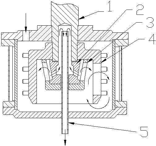
[0013] In order to better understand the present invention, the present invention will be further described below in conjunction with the accompanying drawings. As shown in Figure (1), the centrifugal bead-free separator of the present invention includes: a main shaft 1, a discharge shaft head 2, a separation turbine 3, a rotor 4, and a discharge pipe 5. The discharge shaft head 2, the separation turbine 3 and the rotor 4 are all assembled together with the main shaft, which is actually equivalent to the assembly of three groups of small, medium and large turbines. Due to the centrifugal force generated by the turbines, a working mechanism is formed. In the flow field of circular motion and radial circular motion, the distribution of grinding beads in the flow field is the farther away from the axis, the higher the density. The velocity and energy distribution of the flow field shows that the farther away from the axis, the higher the velocity, the higher the energy density, ...


PUM


Abstract

The invention discloses a centrifugal type partition-net-free material bead separator for a media stirring mill. The centrifugal type partition-net-free material bead separator comprises a main shaft (1), a discharge shaft head (2), a separation turbine wheel (3), a rotor (4) and a discharge pipe (5), wherein the discharge shaft head is provided with a plurality of chutes which are communicated and tangent with an inner circle so as to form a turbine, the turbine is assembled with the separation turbine wheel, the rotor and the main shaft so as to form small, middle and large packaging turbines which generate powerful centrifugal force in a rotating process; milling beads and grinding materials with large particle diameters are thrown out of an outer layer, the grinding materials with small particle diameters bear small centrifugal force so as to overcome the centrifugal force of the turbine under the pressure effect of a pump to enter the discharge pipe to be discharged, the effective segregation of the material beads is ideally realized, and the influence of the diameter sizes of the milling beads is free. The designed separator provided by the invention has the advantages that the manufacturing cost is low, the grinding and dispersion efficiency is greatly improved, the particle diameter of a product after primary grinding is obviously reduced, and compared with a traditional same type grinding machine, the centrifugal type partition-net-free material bead separator has the advantage that the yield is increased by 40-100%.

Description

technical field [0001] The invention belongs to the field of media stirring and grinding equipment, and in particular relates to a centrifugal type bead-free separator for media stirring and grinding. Background technique [0002] At present, the conventional medium-stirred abrasive bead separation devices mainly include dynamic and static ring-type dynamic ring gap separation methods, mesh-type static separation and laminated gap separation methods, which are widely used in coatings, inks, dyes, mining, biology, In the field of ultrafine grinding of medicine and electronic materials. The dynamic and static ring gap separation method only forms an annular discharge gap between the dynamic ring and the static mesh ring. Due to the limited discharge space, under the action of the feed pump, many grinding beads accumulate around the mesh separator and rub against each other to generate a large amount of material. The heat will increase the temperature of the slurry to be groun...

Claims


Application Information

Patent Timeline
Patent Type & Authority Applications(China)
IPC IPC(8): B02C23/12
Inventor 谢小飞
Owner 谢小飞
Why Eureka
Try Eureka