

Winding evaporation type vacuum coating machine
A vacuum coating machine, evaporative technology, applied in the direction of vacuum evaporation coating, sputtering coating, ion implantation coating, etc., can solve the problems of laborious, reduced production efficiency, time-consuming, etc., to improve anti-oxidation ability and improve production The effect of efficiency and simple process
- Summary
- Abstract
- Description
- Claims
- Application Information
AI Technical Summary
Problems solved by technology
Method used
Image

Examples
Embodiment Construction
[0015] The present invention will be described in further detail below in conjunction with the accompanying drawings.
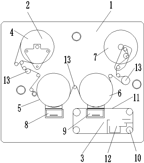
[0016] Such as figure 1 As shown, a roll-to-roll evaporation vacuum coating machine includes a vacuum chamber 1 and a roll-to-roll evaporation system 2 , a shielding system 3 and a motor arranged in the vacuum chamber 1 .
[0017] The winding evaporation system 2 includes a hair reel 4, a No. 1 evaporation drum 5, a No. 2 evaporation drum 6, a winding shaft 7, a No. 1 aluminum evaporator 8 and a No. 2 aluminum evaporator 9; It is arranged in the upper left corner of the vacuum chamber 1, the winding shaft 7 is arranged in the upper right corner of the vacuum chamber 1, and the No. Below the reel 4 and the winding shaft 7; the No. 1 aluminum evaporator 8 is directly below the No. 1 evaporation drum 5, and the No. 2 aluminum evaporator 9 is directly below the No. 2 evaporation drum 6; the shielding system 3 is located in a vacuum chamber 1 lower right corner,...
PUM
 Abstract
Description
Claims
Application Information