
Fluorescence excitation real-time imaging system and method

A real-time imaging system and fluorescence excitation technology, applied in medical science, sensors, diagnostic recording/measurement, etc., can solve the problems of incapable of real-time image imaging, inability to achieve real-time fluorescence imaging and white light real-time imaging, and unsatisfactory real-time imaging effects, etc. To achieve the effect of outstanding features, low R&D cost, and convenient lifting

Active Publication Date: 2013-11-13
BEIJING DIGITAL PRECISION MEDICAL TECH CO LTD
View PDF3 Cites 24 Cited by
  • Summary
  • Abstract
  • Description
  • Claims
  • Application Information

AI Technical Summary

Problems solved by technology

[0005] Excited fluorescence imaging systems currently on the market are roughly divided into two categories: one is to use a single camera for real-time imaging. When this type of product is used for real-time imaging, fluorescence real-time imaging and white light real-time imaging need to be carried out in stages, which cannot be achieved. Simultaneous fluorescence real-time imaging and white light real-time imaging, and the effect of real-time imaging is not ideal
The other is to use multiple cameras for real-time imaging. This type of product has a high imaging resolution and can simultaneously perform real-time imaging of fluorescence data and white light data. However, due to the different chip sizes of fluorescence cameras and white light cameras, and the Data and white light data are transmitted to the computer through two channels respectively, which makes it impossible for this type of product to perform real-time imaging on the fusion image of fluorescence data and white light data

Method used


Image

  • Fluorescence excitation real-time imaging system and method
  • Fluorescence excitation real-time imaging system and method
  • Fluorescence excitation real-time imaging system and method

Examples


Embodiment Construction

[0036] In order to make the object, technical solution and advantages of the present invention clearer, the present invention will be described in detail below in conjunction with specific implementation examples and with reference to the accompanying drawings.

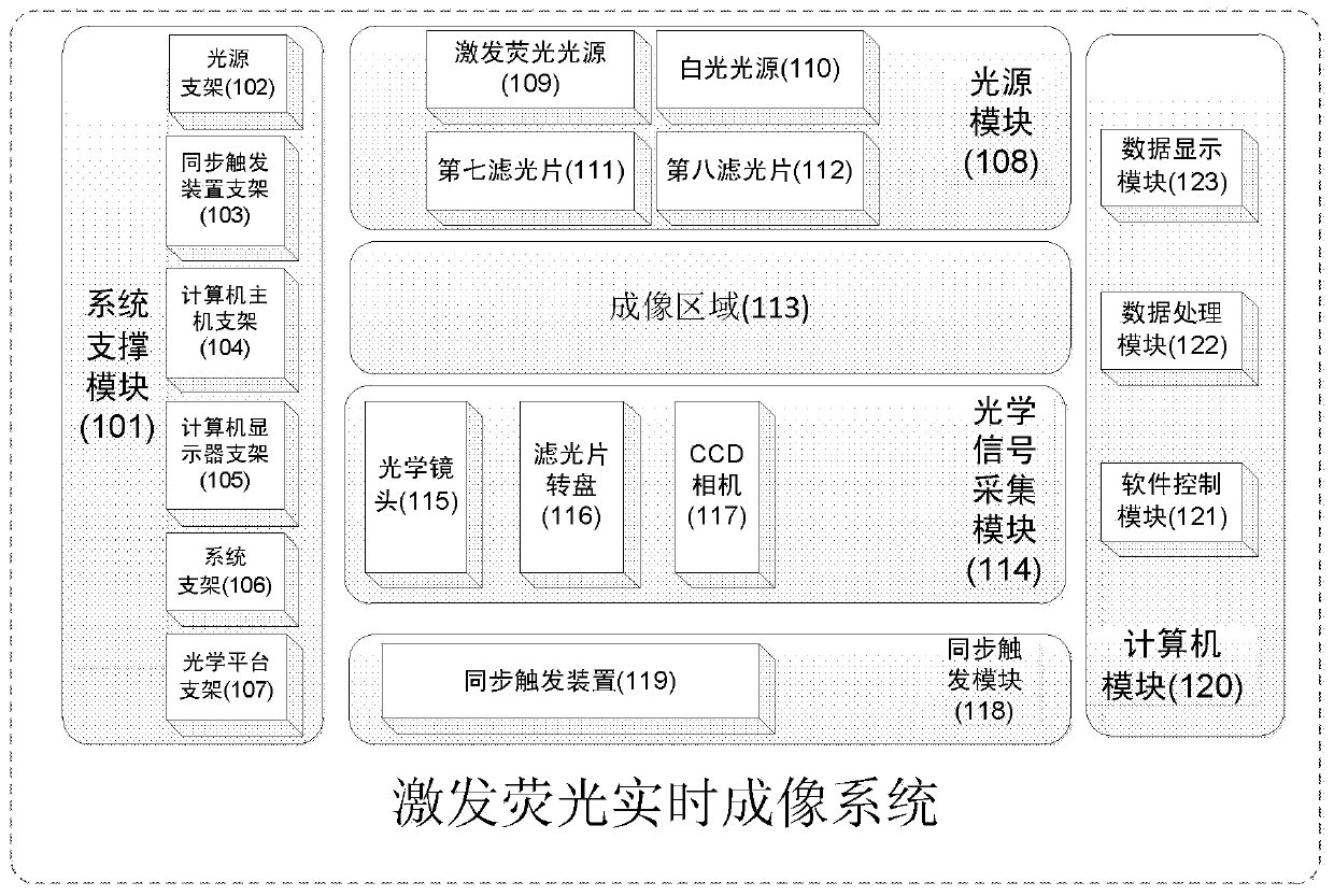
[0037] Such as figure 1 as shown, figure 1 It is a real-time imaging system and method for excited fluorescence according to a preferred embodiment of the present invention. The excited fluorescence real-time imaging system includes an optical signal acquisition module 114 , a light source module 108 , a system support module 101 , a synchronous trigger module 118 , and a computer module 120 . The optical signal acquisition module 114 is used to acquire fluorescence signals and white light signals in the imaging area 113, and mainly includes components such as an optical lens, a filter wheel, and a CCD camera.

[0038] The light source module 108 is used to provide light source illumination to the imaging area 113 ,...


PUM


Abstract

The invention discloses a fluorescence excitation real-time imaging system and method. The system comprises an optical signal acquisition module, a light source module, a system support module, a synchronous triggering module and a computer module, wherein the optical signal acquisition module is used for acquiring optical signals in an imaging area; the light source module is used for providing light source irradiation for the image area; the system support module is used for supporting equipment used in the system; the synchronous triggering module is used for synchronously triggering a CCD (Charge Coupled Device) camera and an optical filter rotating disk; and the computer module is used for performing necessary parameter setting on the system and processing and displaying image data. According to the method and the system, optical fluorescent images and white light images of an object in an imaging visual field can be acquired continuously and dynamically, and fluorescent images and white light images are fused and displayed by using the computer module, so that the problem that a single CCD camera displays continuous and dynamic fused images of the fluorescent images and the white light images is solved effectively. The system is reasonable and practical in structure, can be widely applied to the research of optical molecular image experiments and the research and development of medicines, and has a wide development prospect.

Description

technical field [0001] The invention relates to the technical field of optical molecular imaging, in particular to a real-time imaging system and method for excited fluorescence. Background technique [0002] Molecular imaging is one of the most dazzling sciences and technologies in the 21st century. It refers to the medical imaging technology that detects molecules in living organisms at the molecular level without damage and gives information about the distribution of molecules in the body. And it has been proven to be an imaging tool that can visualize the physiological and pathological changes of organisms at the molecular, gene, and cellular levels in vivo. As one of the important molecular imaging modalities, optical molecular imaging has been applied to the early detection of tumors, Drug development and other fields. [0003] Compared with traditional imaging technologies, optical molecular imaging technology has the following advantages: First, optical molecular i...

Claims


Application Information

Patent Timeline
Patent Type & Authority Applications(China)
IPC IPC(8): A61B5/00
Inventor 田捷叶津佐迟崇巍杨鑫
Owner BEIJING DIGITAL PRECISION MEDICAL TECH CO LTD
Learn More