Paper-based microfluidic chip and preparation method thereof

A microfluidic chip, paper-based chip technology, applied in chemical instruments and methods, laboratory utensils, laboratory containers, etc., can solve the problem of unfavorable liquid control, microstructure effects of migration speed, volatilization and pollution of flowing liquids, etc. problem, to achieve the effect of low cost, simple cross-linking and curing method, and easy portability

Inactive Publication Date: 2013-11-20
GUANGDONG XIAN JIAOTONG UNIV ACADEMY +1
View PDF8 Cites 26 Cited by
  • Summary
  • Abstract
  • Description
  • Claims
  • Application Information

AI Technical Summary

Problems solved by technology

However, since the migration speed of capillary action is mainly affected by the microstructure of the paper-based cellulose, it is not conducive to control the flow behavior of the liquid, and this paper-based microchannel usually exposes the liquid to the air, resulting in the volatilization of the flowing liquid. and pollution

Method used


Image

  • Paper-based microfluidic chip and preparation method thereof
  • Paper-based microfluidic chip and preparation method thereof
  • Paper-based microfluidic chip and preparation method thereof

Examples


Embodiment 1

[0035] Example 1: Preparation of linear paper-based microfluidic chip

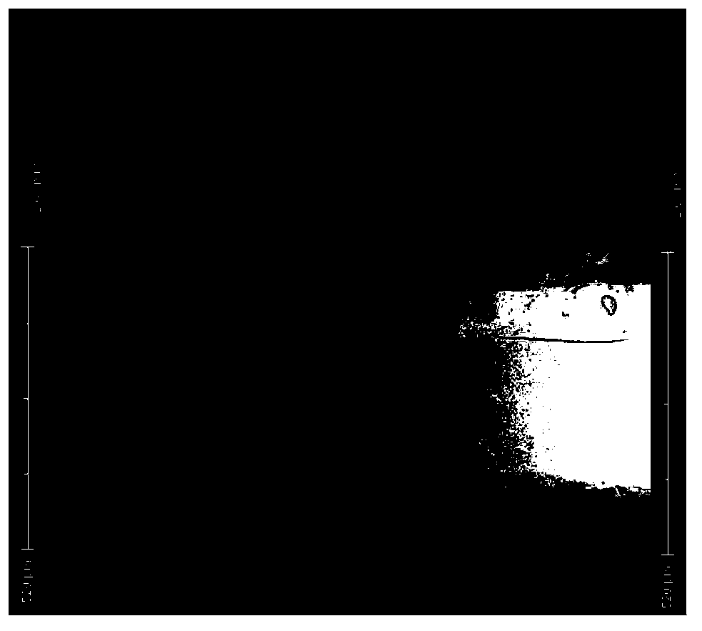
[0036] Use a computer to design a linear microfluidic channel configuration, take a single-layer paper substrate and cut out a paper-based chip that matches the linear channel configuration, and cut out a linear microfluidic channel on the paper-based chip with a laser cutting machine. For the fluidic channel, set the diameter of the microfluidic channel to 300 μm by adjusting the laser intensity (such as figure 1 shown).

[0037] Take a single-layer paper base material, cut out a paper base sheet that matches the paper-based chip with a laser cutting machine, and glue the paper base sheet to the bottom of the paper-based chip with 8146-2 optically transparent adhesive (manufactured by 3M Company in the United States) . Soak the bonded paper-based chip and paper-based sheet in polydimethylsiloxane glue, remove excess polydimethylsiloxane glue, place in an oven, and heat at 60-120°C Bake for 40 minutes t...

Embodiment 2

[0040] Example 2: Preparation of linear paper-based microfluidic chip

[0041] Use a computer to design a linear microfluidic channel configuration, take two layers of paper substrates and cut out paper-based chips that match the linear channel configuration, and use a laser cutting machine to hollow out the two-layer paper-based chips. Create a linear microfluidic channel, and set the diameter of the microfluidic channel to 300 μm by adjusting the laser intensity. Use 8146-2 optically transparent glue to bond two layers of paper-based chips together to form a multi-layer paper-based chip.

[0042] Take a single-layer paper base material, cut out a paper base sheet that matches the multilayer paper-based chip with a laser cutting machine, and glue the paper base sheet to the bottom of the multi-layer paper-based chip with 8146-2 optically transparent glue. Soak the bonded multi-layer paper-based chip and paper-based sheet in polydimethylsiloxane glue, remove excess polydimeth...

Embodiment 3

[0046] Example 3: Preparation of linear three-dimensional paper-based microfluidic chip

[0047] Take the linear paper-based microfluidic chip prepared in Example 1 or Example 2, and fold it to form a linear three-dimensional paper-based microfluidic chip (such as image 3 shown).


PUM


Abstract

The invention discloses a paper-based microfluidic chip. The paper-based microfluidic chip comprises a paper-based chip and a paper-based substrate, wherein the paper-based chip is provided with a microfluidic channel, the paper-based substrate is correspondingly adhered to the bottom of the paper-based chip, and the paper-based chip and the paper-based substrate are respectively subjected to cross-linking and solidifying treatment through liquid glue. The invention also discloses a three-dimensional paper-based microfluidic chip which is formed by stretching or folding the paper-based microfluidic chip. The paper-based microfluidic chip disclosed by the invention has the advantages of low cost, easiness in preparation, controllable liquid flow and the like, and is applicable to microfluidic analysis experiments.

Description

technical field [0001] The invention relates to a microfluidic chip and a preparation method thereof, in particular to a paper-based microfluidic chip and a preparation method thereof. Background technique [0002] The microfluidic chip provides an efficient and fast new reaction platform, which integrates multiple operating units such as sample pretreatment, reaction, separation and detection into a micron-scale chip, and automatically completes the entire reaction process. Control, less sample consumption, fast analysis speed and other advantages, has been widely used in chemistry, biology, medicine and other fields. [0003] Traditional microfluidic chips are based on glass, silicon wafers, polymers, etc., and microchannels are built on these substrates by photolithography and other technologies, and microvalves and micropumps are integrated to form microfluidic chips. . However, the preparation of this microfluidic chip has defects such as complex operation, expensive ...

Claims


Application Information

Patent Timeline
Patent Type & Authority Applications(China)
IPC IPC(8): B01L3/00
Inventor 徐峰韩玉龙王琳卢天健
Owner GUANGDONG XIAN JIAOTONG UNIV ACADEMY
Why Eureka
Try Eureka