Optical fiber micrometric displacement sensor based on Mach-Zehnder interference and manufacturing method of optical micrometric displacement sensor

A technology of a micro-displacement sensor and a manufacturing method, which is applied to instruments, optical devices, coupling of optical waveguides, etc., can solve the problems of high manufacturing cost, low sensitivity, complicated manufacturing procedures, etc., and achieves convenient operation, low cost, and simple process. Effect

Inactive Publication Date: 2013-11-27
浙江尧瑶科技有限公司
View PDF4 Cites 11 Cited by
  • Summary
  • Abstract
  • Description
  • Claims
  • Application Information

AI Technical Summary

Problems solved by technology

Among them, the sensing signal of the reflective intensity-modulated optical fiber micro-displacement sensor depends on the intensity of emitted light and received light, and is easily disturbed by the external environment; The sensing signal eliminates the interference of light intensity fluctuations, and has high reliability and stability. However, the production of these two optical fiber micro-displacement sensors requires sophisticated masks and expensive professional equipment. Not only the production cost is high, but also the production process Complicated; the gap between the two fiber end faces in the Fabry-Peort interferometric optical fiber micro-displacement sensor constitutes a microcavity, and the length of the microcavity changes with the change of the external displacement, resulting in a corresponding change in the interference output signal. The optical fiber micro-displacement sensor has high sensitivity, but because the two optical fiber end faces need to be precisely aligned, it re...

Method used


Image

  • Optical fiber micrometric displacement sensor based on Mach-Zehnder interference and manufacturing method of optical micrometric displacement sensor
  • Optical fiber micrometric displacement sensor based on Mach-Zehnder interference and manufacturing method of optical micrometric displacement sensor
  • Optical fiber micrometric displacement sensor based on Mach-Zehnder interference and manufacturing method of optical micrometric displacement sensor

Examples


Embodiment 1

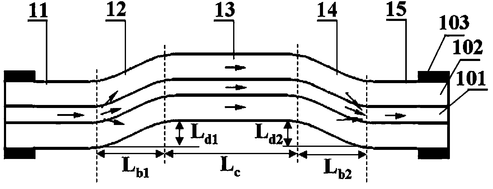
[0026] Embodiment one: a kind of optical fiber micro-displacement sensor based on Mach-Zehnder interference, such as figure 1As shown, it is composed of an input single-mode fiber 11, a first microbend structure fiber 12, a conduction single-mode fiber 13, a second microbend structure fiber 14 and an output single-mode fiber 15, and light passes through the core of the input single-mode fiber 11 Transmitted into the first microbend structure fiber 12, the light is divided into two parts in the first microbend structure fiber 12, a part of the light remains in the core of the first microbend structure fiber 12 to propagate in the core fundamental mode, and the other part of the light Enter the cladding of the first microbend structure fiber 12 to propagate in the cladding mode, and the light propagated in the core fundamental mode output by the first microbend structure fiber 12 is transmitted to the second microbend through the core of the conductive single-mode fiber 13 In th...

Embodiment 2

[0037] Embodiment 2: The method for preparing the optical fiber micro-displacement sensor in this embodiment is the same as that of Embodiment 1, only the structural parameters of the optical fiber micro-displacement sensor are different, namely: the length L of the conductive single-mode optical fiber 13 C =2.5mm; the vertical distance L between the planes where the two ends of the first microbending structure optical fiber 12 are located b1 =745 μm, the vertical distance L between the planes where the two ends of the second microbend structure optical fiber 14 are located b2 =762 μm; the radial offset L of the first microbend optical fiber 12 d1 =100 μm, the radial offset L of the second microbend structure optical fiber 14 d2 =110μm.

Embodiment 3

[0038] Embodiment 3: The manufacturing method of preparing the optical fiber micro-displacement sensor in this embodiment is the same as that of Embodiment 1, only the structural parameters of the optical fiber micro-displacement sensor are different, that is: the length L of the conductive single-mode optical fiber C =11.5mm; the vertical distance L between the planes where the two ends of the first microbending structure optical fiber 12 are located b1 =743 μm, the vertical distance L between the planes where the two ends of the second microbending structure optical fiber 14 are located b2 =752 μm; the radial offset L of the first microbend optical fiber 12 d1 =102 μm, the radial offset L of the second microbend fiber 14 d2 =105 μm.


PUM

PropertyMeasurementUnit
Lengthaaaaaaaaaa
Lengthaaaaaaaaaa
Lengthaaaaaaaaaa

Abstract

The invention discloses an optical fiber micrometric displacement sensor based on Mach-Zehnder interference and a manufacturing method of the optical micrometric displacement sensor. The optical fiber micrometric displacement sensor is composed of an input single mode optical fiber, a first micrometric bending structure optical fiber, a conductive single mode optical fiber, a second micrometric bending structure optical fiber and an output single mode optical fiber; light is transmitted to the first micrometric bending structure optical fiber through the input single mode optical fiber and is divided into two parts in the first micrometric bending structure optical fiber; one part is transmitted as a fiber core basic mode in the first micrometric bending structure optical fiber; the other part is transmitted as a cladding mode in cladding of the first micrometric bending structure optical fiber; light transmitted as the fiber core basic mode is transmitted to a fiber core of the second micrometric bending structure optical fiber through the conductive single mode optical fiber; light transmitted as the cladding mode is transmitted to cladding in the second micrometric bending structure optical fiber through the conductive single mode optical fiber; part of the light transmitted as the cladding mode is coupled with the fiber core of the second micrometric bending structure optical fiber and interference light is formed by the light coupled with the fiber core and the light transmitted as the fiber core basic mode and the interference light is output through the output single mode optical fiber; the optical fiber micrometric displacement sensor based on Mach-Zehnder interference has the advantages of being high in sensitivity, simple in manufacture and low in cost.

Description

technical field [0001] The invention relates to an optical fiber sensing technology, in particular to an optical fiber micro-displacement sensor based on Mach-Zehnder interference and a manufacturing method thereof. Background technique [0002] When light is transmitted in the optical fiber, the characteristic parameters (such as amplitude, phase, polarization state, wavelength, etc.) that characterize the light wave will occur directly or indirectly due to external factors (such as temperature, refractive index, pressure, displacement, vibration, rotation, etc.) The optical fiber sensor is a kind of optical fiber sensing element that uses this basic principle to detect external physical quantities. Compared with ordinary photoelectric sensors, optical fiber sensors have the advantages of light weight, small size, anti-electromagnetic interference, electrical insulation, corrosion resistance, high sensitivity and long-distance control, and can effectively perform sensing op...

Claims


Application Information

Patent Timeline
IPC IPC(8): G01B11/02G02B6/255G02B6/25
Inventor 周骏陈金平张琪束磊姜涛
Owner 浙江尧瑶科技有限公司
Why Eureka
Try Eureka