
Fuel Injection Control System for Internal Combustion Engine

A fuel injection and control system technology, applied in fuel injection control, engine control, internal combustion piston engine, etc., can solve the problems of liquid fuel entering the cylinder, increasing the possibility of soot, toxic unburned components, etc., to reduce dilution and accurately predict Pre-ignition, the effect of reducing pre-ignition combustion events

Inactive Publication Date: 2016-07-06
SUZUKI MOTOR CORP
View PDF10 Cites 0 Cited by
  • Summary
  • Abstract
  • Description
  • Claims
  • Application Information

AI Technical Summary

Problems solved by technology

However, injecting fuel into the cylinder during the intake stroke can cause an increase in HC (hydrocarbon) and CO (carbonmonoxide, carbon monoxide), which are toxic unburned components
Additionally, injecting fuel into the cylinder during the intake stroke can cause liquid fuel to enter the cylinder, increasing the likelihood of soot

Method used


Image

  • Fuel Injection Control System for Internal Combustion Engine
  • Fuel Injection Control System for Internal Combustion Engine
  • Fuel Injection Control System for Internal Combustion Engine

Examples


Embodiment Construction

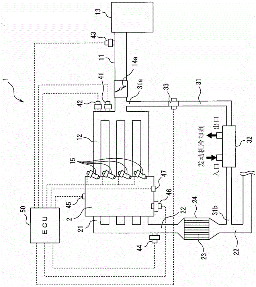
[0064] Embodiments of the present invention are described with reference to the drawings. As the present embodiment, a vehicle having an internal combustion engine fuel injection control system will be described.

[0065] figure 1 is a schematic diagram of an exemplary configuration of the vehicle 1 according to the present embodiment. Such as figure 1 As shown in , according to the present embodiment, the internal combustion engine 2 mounted to the vehicle 1 is a four-stroke internal combustion engine 2 . Furthermore, according to the present embodiment, the internal combustion engine 2 is a four-cylinder internal combustion engine.

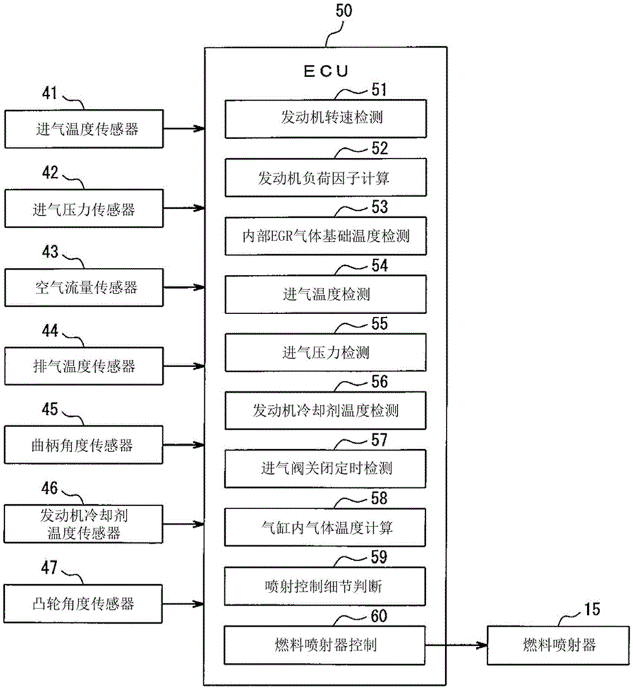
[0066] In the intake system of the internal combustion engine 2 , an intake passage 11 is connected to an intake manifold 12 communicating with a combustion chamber of each cylinder of the internal combustion engine 2 . The intake passage 11 includes an air cleaner 13 on the upstream side thereof and an electronically controlled throttle bod...


PUM


Abstract

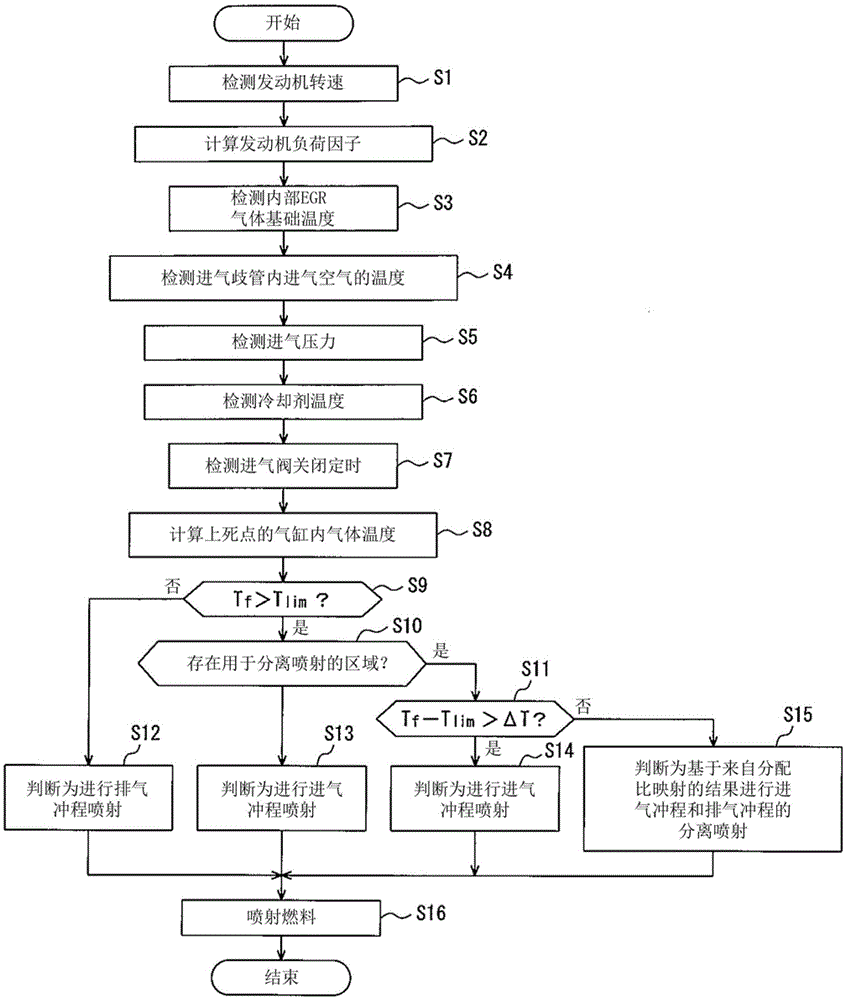
Provided is a fuel injection control system for an internal combustion engine. Fuel is injected from a fuel injector for port injection upstream of the intake valve during the exhaust stroke. Predicts the in-cylinder temperature at which the engine cylinders undergo compression. When it is determined that the predicted in-cylinder temperature is greater than a temperature at which pre-ignition is expected to occur, fuel is injected from the fuel injector during an intake stroke to supply fuel to the interior of the cylinder.

Description

technical field [0001] The present invention relates to fuel injection control techniques particularly for controlling the operation of fuel injection valves in internal combustion engines. Background technique [0002] Traditionally, under high load or high EGR (EGR: ExhaustGasRecirculation, exhaust gas recirculation, including external EGR and internal EGR) operating conditions, engines with high compression ratios may be prone to pre-ignition combustion events on many occasions become a problem. [0003] The tendency for pre-ignition combustion events to occur arises from: a higher compression ratio caused by increased intake of combustible charge into the cylinder during high load operation than during low load driving; Increased recirculation of high-temperature exhaust gas results in an increase in cylinder temperature. This pre-ignition combustion event can cause very high in-cylinder pressures and can lead to severe damage to the piston and cylinder head in the cyl...

Claims


Application Information

Patent Timeline
Patent Type & Authority Patents(China)
IPC IPC(8): F02D41/22F02D41/30
CPCF02D41/345F02D35/026F02D2041/1412Y02T10/40F02D41/00
Inventor 栗山纱子稻田弘树
Owner SUZUKI MOTOR CORP
Learn More