High-pressure gas preservation method

A high-pressure gas and compressed gas technology, applied in the field of high-pressure gas storage, can solve the problems of high operating costs and large floor space, and achieve the effects of strong construction adaptability, low maintenance costs, and small chances of leakage

Inactive Publication Date: 2013-12-04
COOEC ENPAL ENG
View PDF4 Cites 8 Cited by
  • Summary
  • Abstract
  • Description
  • Claims
  • Application Information

AI Technical Summary

Problems solved by technology

Utilizing depleted oil fields and gas fields to build underground gas storage, it is necessary to know the porosity, permeability, presence or absence of water immersion phenomenon, structural shape and size, thickness of oil and gas rock formations, and accurate data about the wellbore and well structure of the gas storage formation. and the reliability of the isolation between strata and adjacent strata, etc.; the use of water-bearing porous strata to build a gas storage requires it to be composed of water-bearing sand layers and impermeable layers, and generally the water-bearing sand layer is 400-700 meters to be economically feasible; the use of salt caverns and To build a gas storage in the salt mine layer, it is necessary to store natural gas in the cavities formed after the salt layer is melted and pumped away, but the existing gas storage forms all require a large amount of bottom gas (continuously retained in the storage or used as a gap between the working gas and water) cushion gas), and there will be a small amount of bottom gas diffusion, and a part of bottom gas must be supplemented every year, which is about 6% of the working gas (gas stored and re-discharged during the storage cycle), high operating costs, accounting for Large area

Method used


Image

  • High-pressure gas preservation method
  • High-pressure gas preservation method

Examples


Embodiment

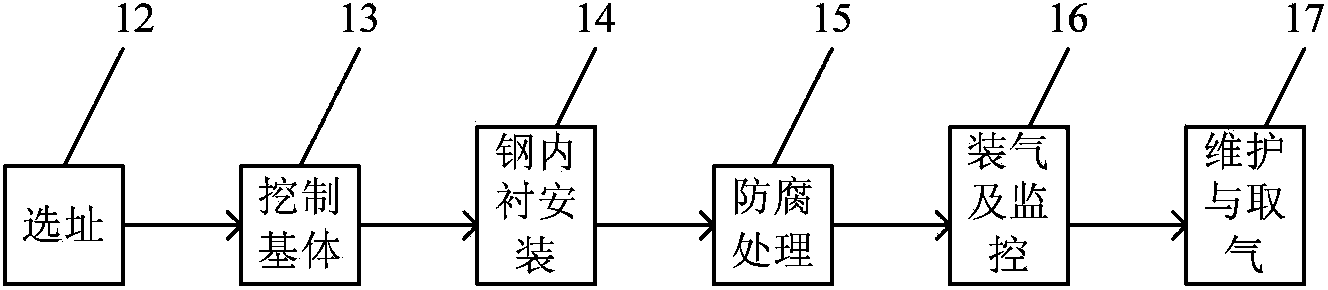
[0022] The process steps of this embodiment include site selection, excavation of substrate, installation of steel lining, anti-corrosion treatment, gas filling and monitoring, maintenance and gas extraction;

[0023] (1) Site selection: first select an area with a hard geological structure within the determined area as the gas storage site. The geographical conditions of the selected gas storage site are that the range of 10 to 150 meters below the ground level is a hard geographical environment, and the hard index Rocky and sandy soil, less groundwater;

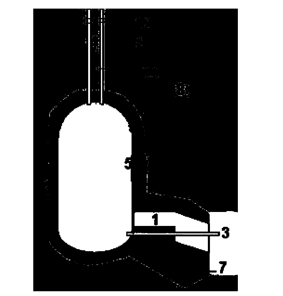
[0024] (2) Excavating the substrate: At the selected gas storage location, excavate the hollow or embedded concave substrate manually or mechanically, and the structural shape and size of the substrate are larger than the size of the steel lining; the excavation method is Open-pit excavation or tunnel drilling; construction passages or workshops are left at the bottom of the substrate to facilitate the installation of steel...


PUM


Abstract

The invention belongs to the technical field of gas storage, and relates to a preservation method of high-pressure gas deeply embedded underground. According to the invention, an area with hard geological structure is selected as a gas preservation site; a base is dug on the selected gas preservation site; a construction channel or a working chamber is preserved in the base; a cylindrical steel liner is welded in the inner cavity of the base through the construction tunnel and the working chamber; network steel bar concrete or network steel bar asphalt mixture is filled in the space between the steel liner and the base, and an anti-corrosion treatment is carried out on the periphery of the steel liner; compressed gas to be stored is filled into the steel liner through a gas inlet pipe and a valve on the top of the steel liner under the control of a compression pump, and the state in the steel liner is controlled through a monitoring device; high-pressure gas stored in the steel liner is monitored regularly, such that gas pressure, temperature, water content, and density parameters of high-pressure gas stored in the steel liner are controlled in real time. The process principle is reliable, storage safety is good, control is flexible, operation cost is low, and the method is environment-friendly.

Description

Technical field: [0001] The invention belongs to the technical field of gas storage, and relates to a gas storage method for storing high-pressure natural gas, high-pressure air, high-pressure carbon dioxide gas and high-pressure hydrogen gas under normal temperature conditions by using a gas storage device with a steel lining structure. In the inner cavity of the lining gas storage device, it is used for strategic reserves, emergency reserves and peak shaving reserves, especially a high-pressure gas storage method embedded deep underground. Background technique: [0002] As a clean energy, the consumption of natural gas is increasing, and the market is in short supply. The process of urbanization, energy conservation and emission reduction also promote the rapid growth of natural gas consumption. Natural gas consumption has tripled in the past decade and will continue to grow at the same rate in the next decade. Natural gas is gradually replacing other highly polluting ene...

Claims


Application Information

Patent Timeline
IPC IPC(8): F17C1/10F17C13/02F17C13/04F17C13/00E21F17/16
Inventor 王金昌杨森于连兴李俊彦彭振华
Owner COOEC ENPAL ENG
Why Eureka
Try Eureka