Microglow discharge ionization source integrated faims

A technology of glow discharge and ionization source, applied in ion source/gun, parts of particle separator tube, material analysis by electromagnetic means, etc., can solve the problems of electric field interference, affecting the stability and sensitivity of the device, etc.

Active Publication Date: 2016-08-10
SUZHOU INDAL TECH RES INST OF ZHEJIANG UNIV
View PDF4 Cites 0 Cited by
  • Summary
  • Abstract
  • Description
  • Claims
  • Application Information

AI Technical Summary

Problems solved by technology

[0006] The technical problem to be solved by the present invention is that the ion source in the integrated miniature high-field asymmetric waveform ion mobility spectrometer in the prior art must have a large ionization voltage, which will cause electric field interference to other areas and affect the stability and sensitivity of the device. In order to provide a microglow discharge ionization source integrated FAIMS with high stability and sensitivity and easy production

Method used


Image

  • Microglow discharge ionization source integrated faims
  • Microglow discharge ionization source integrated faims

Examples


Embodiment 1

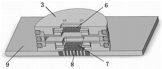
[0029] The structure of microglow discharge ionization source integrated FAIMS described in the present invention is as follows: figure 1As shown, it includes a PCB board 9 and a supporting and fixing board 3, one end of the supporting and fixing board 3 is connected to the PCB board 9, and the other end is an open end, and an air inlet and a power interface are arranged on the open end ; The inside of the fixed support plate is provided with a microglow discharge ionization source 6, a FAIMS chip 7 and a detector 8 sequentially from the open end to the connection end, and the detector 8 is arranged on the PCB board 9, and the The air inlet, the micro-glow discharge ionization source 6 , the FAIMS chip 7 and the detector 8 form a passage through the support and fixing plate 3 and the PCB board 9 . The sample enters the sample channel from the air inlet port, and the sample is ionized by the micro-glow discharge ion source. When the distance between the two electrodes is 50 mic...

Embodiment 2

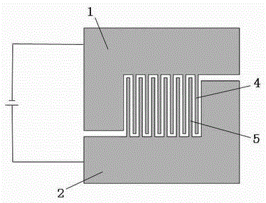
[0031] The micro-glow discharge ionization source 6 in the micro-glow discharge ionization source integrated FAIMS of the present invention is as follows: figure 2 As shown, the microglow ionization source includes positive discharge electrodes 2 and negative discharge electrodes 1, and positive electrode flow guide plates 5 and negative electrode flow guide plates 4 are alternately arranged oppositely between the positive discharge electrodes 2 and negative discharge electrodes 1, Only one end of the positive deflector 5 is connected to the positive discharge electrode 2; only one end of the negative deflector 4 is connected to the negative discharge electrode 1; the positive deflector 5 and the negative deflector 4 to form a continuous channel, the number of the positive discharge electrodes 2 and the negative discharge electrodes 1 can be adjusted according to actual needs, and it is preferably a silicon chip, the thickness of the silicon chip is 0.1-5mm. The most preferre...

Embodiment 3

[0034] A plurality of ion migration channels are etched in the middle of the FAIMS chip 7 in the microglow discharge ionization source integrated FAIMS of the present invention along the longitudinal direction on the silicon wafer. The pitch of each channel is preferably 20-500 microns, and the depth of the channels is preferably 200-3000 microns. An asymmetric radio frequency high voltage is preferably added to the two electrodes of the FAIMS chip 7, and the frequency is preferably 0.2-30 MHz to realize an environment in which high and low electric fields alternately change.


PUM


Abstract

A microglow discharge ionization source integrated FAIMS, including a PCB board and a support fixed plate, one end of the support fixed plate is connected to the PCB board, and the other end is an open end, and the open end is provided with a further Air port and power interface; inside the fixed support plate, a microglow discharge ionization source, a FAIMS chip and a detector are sequentially arranged from the open end to the connecting end, and the detector is arranged on the PCB board, and the The air inlet, the micro-glow discharge ionization source, the FAIMS chip and the detector form a passage through the support fixing plate and the PCB board; the present invention uses a micro-glow discharge ionization source with a special structure to reduce ionization The voltage applied by the source reduces the impact on other devices, increases stability and sensitivity, and is processed by MEMS technology, which is smaller overall and has a lower external voltage, making the application more convenient and wider.

Description

technical field [0001] The invention relates to a rapid detection device for biochemical substances, in particular to a microglow discharge ionization source integrated FAIMS, which belongs to the technical field of on-site analysis and detection. Background technique [0002] Field Asymmetric Waveform Ion Mobility Spectrometry (FAIMS) technology is a mobility spectrometry technology developed by scientists in the former Soviet Union. It was first published by Buryakov et al. in the early 1990s. Traditional ion mobility spectrometry technology mainly relies on the difference in the mobility of various ions under low electric field (<1000 V / cm), and the drift time of sample ions reaching the detector to separate and identify different compounds to achieve the purpose of analysis and detection. At low electric fields (<1000 V / cm), the ion mobility of a species is a constant constant independent of the field strength. However, under high electric field (>10000 V / cm), ...

Claims


Application Information

Patent Timeline
Patent Type & Authority Patents(China)
IPC IPC(8): H01J49/10H01J49/26
CPCG01N27/624
Inventor 李灵锋汪小知李鹏
Owner SUZHOU INDAL TECH RES INST OF ZHEJIANG UNIV
Why Eureka
Try Eureka