Finish machining method of direct lathe machining of optical collecting mirror in EUV (extreme ultra-violet) lithography light sources

A technology of extreme ultraviolet lithography and collecting mirrors, which is applied in the direction of turning equipment, turning equipment, metal processing equipment, etc., to achieve the effects of high processing precision, short cycle time and saving processing cost

Active Publication Date: 2013-12-11
HARBIN INST OF TECH
View PDF6 Cites 13 Cited by
  • Summary
  • Abstract
  • Description
  • Claims
  • Application Information

AI Technical Summary

Problems solved by technology

[0005] The object of the present invention is to provide a method for direct turning and finishing of the optical collection mirror in the extreme ultraviolet lithography light source, so as to solve the problem of using the replication method to process the optical collection mirror in the EUV light source. Matching solid shaft, and nickel deposition treatment is carried out on the surface of the solid shaft, and then the nickel shell is peeled off to form the base of the collecting mirror

Method used


Image

  • Finish machining method of direct lathe machining of optical collecting mirror in EUV (extreme ultra-violet) lithography light sources
  • Finish machining method of direct lathe machining of optical collecting mirror in EUV (extreme ultra-violet) lithography light sources
  • Finish machining method of direct lathe machining of optical collecting mirror in EUV (extreme ultra-violet) lithography light sources

Examples


specific Embodiment approach 1

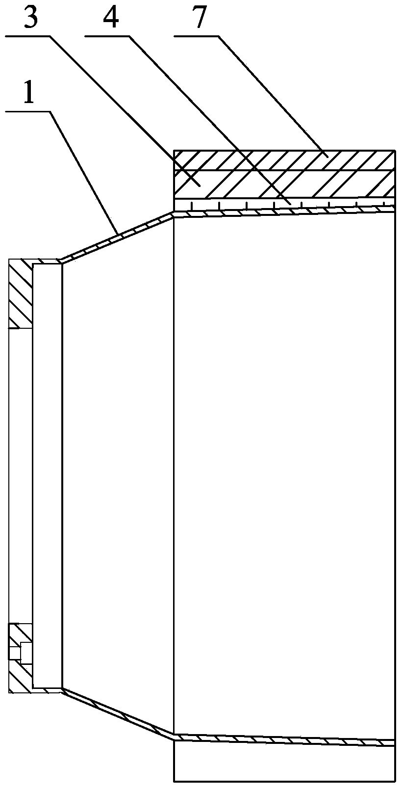
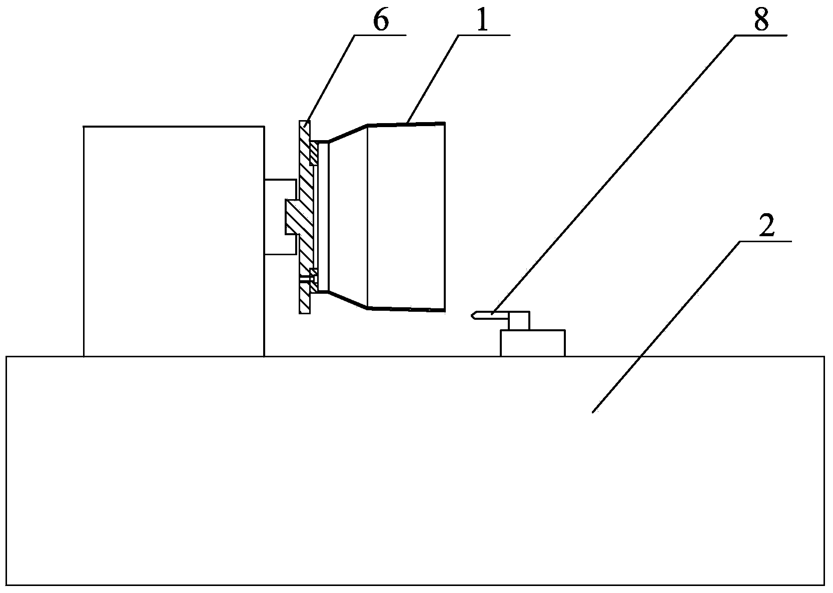
[0020] Specific implementation mode one: combine figure 2 with image 3 To illustrate, the direct turning and finishing method of the optical collecting mirror in the extreme ultraviolet lithography light source of the present embodiment, the method includes the following steps:

[0021] The first step: install the collection lens tube blank 1; firstly install the collection lens tube blank 1 after rough turning, the surface shape of the collection lens tube blank 1 is composed of hyperboloid and ellipsoidal surface (the collection lens tube blank 1 The surface shape is the inner surface of the collecting lens barrel blank 1), and the collecting lens barrel blank 1 (inner surface) is corrected to ensure that the runout value is within the range of 0.1mm to 0.5mm;

[0022] Step 2: Rough turning in finishing turning; use the finishing lathe to carry out rough turning in finishing turning on the collection lens tube blank 1, each feed is 0.04-0.06mm, and the number of times of ...

specific Embodiment approach 2

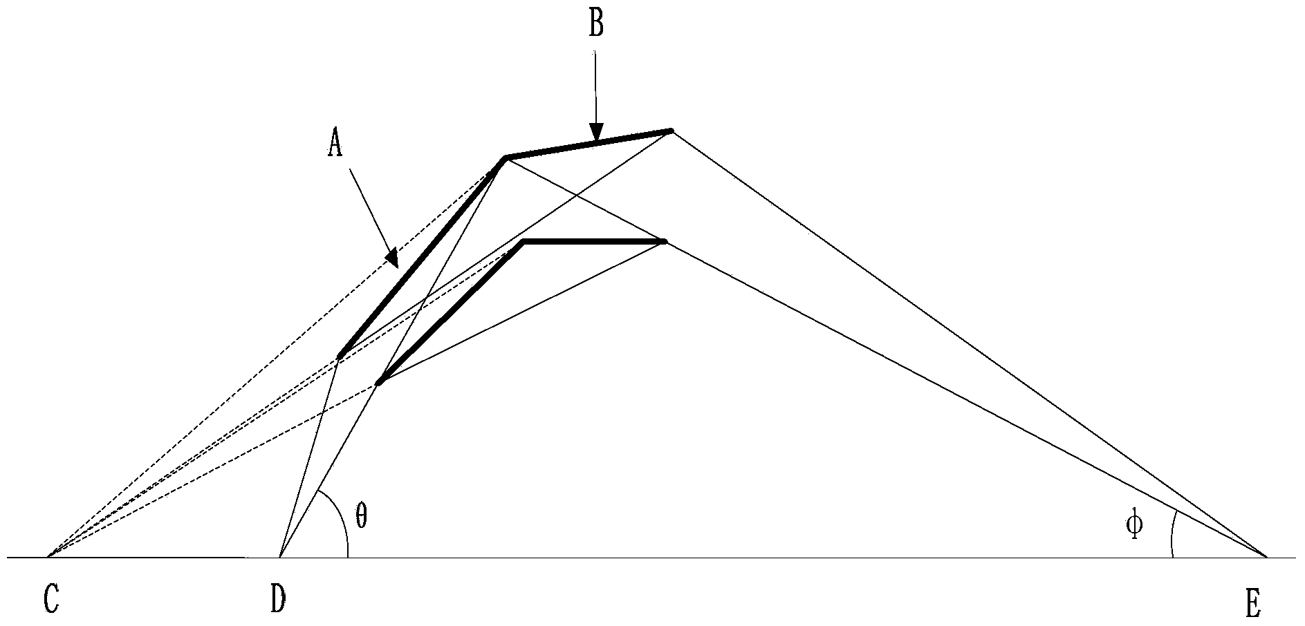
[0028] Specific implementation mode two: combination figure 1 Illustrate that the rough turning process of the collecting lens barrel blank 1 in the first step of the present embodiment is realized in the following way: firstly, the aluminum alloy blank is rough turned into a cylindrical workpiece with a common numerically controlled lathe, and the wall thickness of the cylindrical workpiece is 6.5 mm. , and then turned by an ordinary CNC lathe according to the collection mirror type and leave the margin required for the finish car, the margin is 0.5 ~ 1mm, and then undergo 7-8 dimensional stabilization treatments (to ensure the dimensional stability of the aluminum alloy material and meet the requirements of the collection process). mirror application requirements) and then made into a collecting mirror tube blank 1. The undisclosed technical features in this embodiment are the same as those in the first embodiment.

specific Embodiment approach 3

[0029] Specific implementation mode three: combination figure 2 Explain that in the fourth step of the present embodiment, before the finish car, the outer surface of the collecting lens barrel blank 1 completed in the third step is covered with a nylon sleeve 3, and the nylon sleeve 3 is covered by vacuum cement 4. Sticking on the outer surface of the collecting lens barrel blank 1 can ensure the processing in a rigid state. Strictly control the counterweight (through slow rotation, measure the rotational speed and eccentricity changes during rotation, and the center of the counterweight is located at the axis of the entire lens). The undisclosed technical features in this embodiment are the same as those in the first embodiment.


PUM

PropertyMeasurementUnit
thicknessaaaaaaaaaa
surface roughnessaaaaaaaaaa

Abstract

The invention discloses a finish machining method of direct lathe machining of an optical collecting mirror in EUV (extreme ultra-violet) lithography light sources, belongs to the field of optics and finish machining, and aims at solving the problems that the optical collecting mirror in EUV light sources is machined by adopting a reproducible method, firstly a solid shaft which is matched with the surface type of the required collecting mirror is required to be machined, then the surface of the solid shaft is subjected to nickel deposition treatment, and then the nickel shell is peeled to form a substrate of the collecting mirror. According to the technique of the scheme, the accuracy control required during the machining process is very strict, and the machining cost is increased. The method comprises the following steps: installing and clamping a cylinder blank 1 of the collecting mirror; carrying out rough lathe machining in finish lathe machining; carrying out half-finish lathe machining; carrying out the finish lathe machining; carrying out membrane coating treatment; carrying out manual polishing treatment; carrying out the manual polishing treatment on the surface type of the cylinder blank of the collecting mirror after the membrane coating treatment, so that the surface type of the cylinder blank of the collecting mirror meets the surface type of the collecting mirror, thereby completing the manufacture of the collecting mirror. The finish machining method provided by the invention is used for machining and manufacturing the optical collecting mirror in the EUV lithography light sources.

Description

technical field [0001] The invention belongs to the field of optics and precision machining, and in particular relates to a method for direct turning and finishing of an optical collecting mirror in an extreme ultraviolet lithography light source. Background technique [0002] The photolithography technology whose lithography width is below 100nm is called extreme ultraviolet lithography technology. Among them, realizing the reticle of 22nm to 45nm has become the development goal of my country's extreme ultraviolet lithography light source by 2020. At present, there are mainly two kinds of extreme ultraviolet lithography light sources in the world to achieve this goal: laser plasma (LPP) and discharge plasma (DPP). % bandwidth) radiated light output. DPP light sources mainly include technical solutions such as capillary discharge, hollow cathode tube, and plasma focus. Among them, the capillary discharge ultraviolet lithography light source is a very important light source...

Claims


Application Information

Patent Timeline
Patent Type & Authority Applications(China)
IPC IPC(8): B23B5/00B23B1/00B23P15/00
Inventor 徐强赵永蓬王骐
Owner HARBIN INST OF TECH
Why Eureka
Try Eureka