Cutting hydraulic system of cutting machine

A hydraulic system and cutting machine technology, applied in metal processing, etc., can solve problems such as abnormal hydraulic clutch, poor working environment for employees, and high vibration and noise of machines, so as to reduce abnormal vibration and noise of equipment and ensure oil viscosity Effects of performance and equipment life extension

Active Publication Date: 2015-09-23
JIANGSU GENERAL SCI TECH
View PDF7 Cites 0 Cited by
  • Summary
  • Abstract
  • Description
  • Claims
  • Application Information

AI Technical Summary

Problems solved by technology

[0005] The existing hydraulic system has the following problems: (1) The hydraulic overflow is realized by the filling valve and the overflow valve. The oil overflows at a high speed in the small damping hole in the valve body, and friction generates heat; the oil pump adopts a quantitative pump, regardless of cutting Action or not, the oil pump always works and generates heat; when the heat temperature is close to 60 degrees, the viscosity of the oil will drop significantly and the leakage will increase, resulting in abnormal operation of the hydraulic clutch; (2) When cutting the cutting machine, it is necessary to have A certain speed and inertial mass can cut the material. When the eccentric shaft is at the top dead center and the bottom dead point, the moving speed of the slider is zero and the acceleration is the largest, so the vibration and noise of the machine are large, which affects the life of the machine and the working environment of the employees is not good.

Method used


Image

  • Cutting hydraulic system of cutting machine
  • Cutting hydraulic system of cutting machine

Examples


Embodiment Construction

[0016] The present invention will be further described below in conjunction with specific drawings.

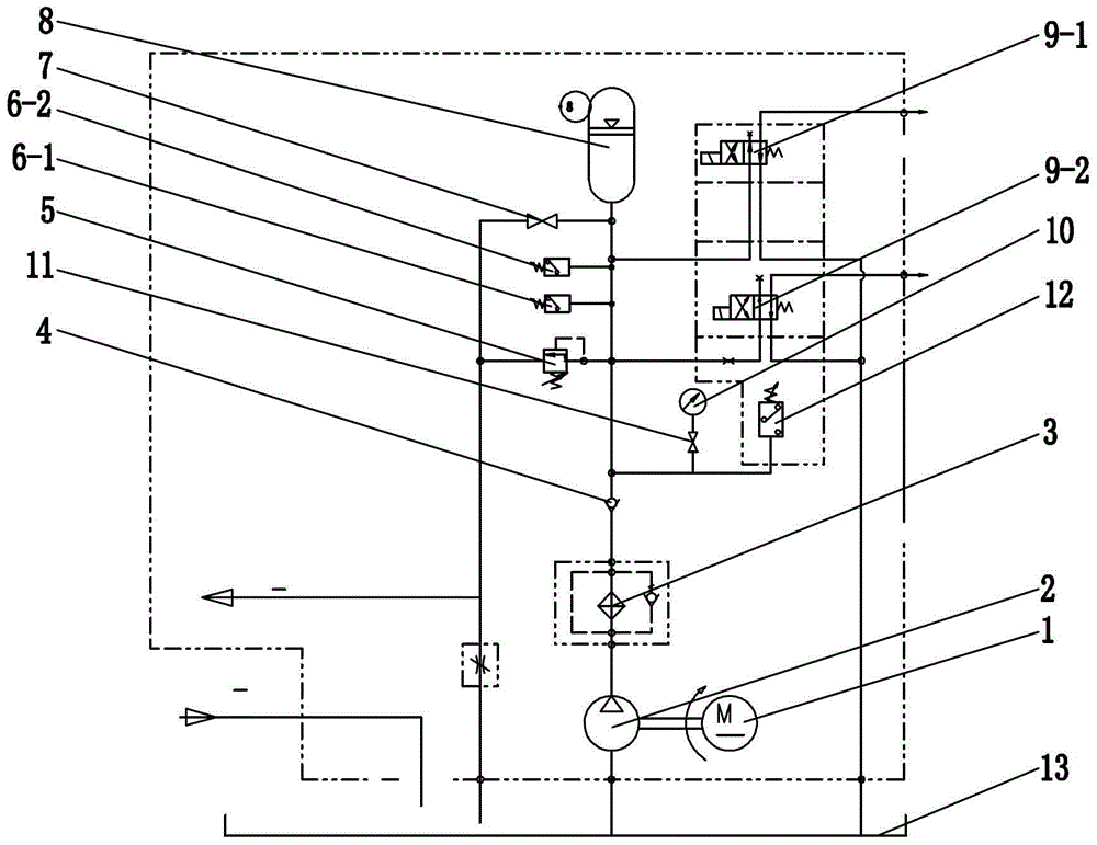
[0017] Such as figure 2 As shown: the cutting hydraulic system of the cutting machine includes a motor 1, an oil pump 2, an oil filter 3, a one-way valve 4, an overflow valve 5, a first pressure relay 6-1, a second pressure relay 6-2, a cut-off Valve 7, accumulator 8, first reversing valve 9-1, second reversing valve 9-2, pressure gauge 10, pressure gauge switch 11, third pressure relay 12, fuel tank 13, etc.

[0018] Such as figure 2 As shown, the present invention includes an oil pump 2, the input end of the oil pump 2 is connected to the oil tank 13, the output end of the oil pump 2 is connected to the input end of the oil filter 3, the output end of the oil filter 3 is connected to the input end of the one-way valve 4, and the one-way valve 4 The output terminals of the output ports are respectively connected to the accumulator 8, the overflow valve 5, the first pressu...


PUM


Abstract

The invention relates to a hydraulic cutting system of a cutting machine. The hydraulic cutting system of the cutting machine comprises an oil pump, the input end of the oil pump is connected with an oil tank, the output end of the oil pump is connected with the input end of an oil filter, and the output end of the oil filter is connected with the input end of a check valve. The hydraulic cutting system of the cutting machine is characterized in that the output end of the check valve is connected with an energy accumulator, an overflow valve, a first pressure relay, a second pressure relay, a third pressure relay, a first reversing valve and a second reversing valve, and the oil outlet of the second reversing valve is connected with a hydraulic clutch of the cutting machine. A stop valve is arranged between the overflow valve and the energy accumulator. The oil return opening of the first reversing valve and the oil return opening of the second reversing valve are connected with the oil tank. The third pressure relay is connected with a pressure gage and a pressure gage switch. One end of the overflow valve is connected with the output end of the check valve, and the other end of the overflow valve is connected into the oil tank. The power input end of the oil pump is connected with a motor. According to the hydraulic cutting system of the cutting machine, idle consumption heating of the hydraulic system is reduced, the viscosity performance of oil is ensured, and the service life of the oil is prolonged.

Description

technical field [0001] The invention relates to a cutting hydraulic system, in particular to a cutting hydraulic system of a cutting machine, which belongs to the field of hydraulic technology. Background technique [0002] The principle of the cutting machine is: mechanical cutting is to convert the rotary motion into linear reciprocating motion, and convert the rotary motion through the eccentric shaft device into the up and down motion of the upper cutter. When the eccentric shaft rotates from the top dead point to the bottom dead point, it is the process of cutting downward; when the eccentric shaft continues to rotate from the bottom dead point to the top dead point, the process of lifting the cutting knife is realized. [0003] Intermittent cutting control is mainly realized through the instantaneous engagement and disengagement of the hydraulic clutch. When the beveling signal of the cutting machine is obtained, the clutch engages to drive the eccentric shaft to rota...

Claims


Application Information

Patent Timeline
Patent Type & Authority Patents(China)
IPC IPC(8): B26D5/12B26F1/38
Inventor 陈刚
Owner JIANGSU GENERAL SCI TECH
Why Eureka
Try Eureka