Oil pipeline leakage detection and positioning system

A leak detection and positioning system technology, applied in pipeline systems, gas/liquid distribution and storage, mechanical equipment, etc., can solve the problems of low accuracy, difficult detection, high cost, reduce accumulated clock errors, save wired resources, and locate simple effect

Inactive Publication Date: 2013-12-11
毛振刚
View PDF0 Cites 27 Cited by
  • Summary
  • Abstract
  • Description
  • Claims
  • Application Information

AI Technical Summary

Problems solved by technology

[0003] In order to detect the leakage of pipelines in time, reduce economic losses, and fight against criminals, many methods have been studied at home and abroad for monitoring, but the results are not ideal. For example, direct observation method, experienced technicians carry detection equipment or trained Leakage detection and positioning of pipelines by animals in sections, and judging whether there is leakage by seeing, smelling, listening or other methods. This method has the characteristics of high positioning accuracy and low false alarm rate, but it cannot detect leakage in time , the detection can only be carried out intermittently; the flow balance method is based on the law of material conservation. Under normal circumstances, the flow at the inlet port should be equal to the flow at the outlet port. In the case of flow leakage, there is also a leakage location calculation formula in theory, but it has not been successfully applied in practice; the pressure difference method is based on the law of energy conservation. Under normal circumstances, the difference between the inlet pressure and the outlet pressure should be a constant value. If the pressure If there is a large change in the difference, it means that there is a leak in the middle, but this

Method used


Image

  • Oil pipeline leakage detection and positioning system

Examples


Embodiment Construction

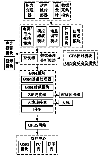
[0018] Embodiments of the present invention are described in further detail below in conjunction with the accompanying drawings:

[0019] An oil pipeline leakage detection and positioning system, its main technical features are: including data acquisition module, signal conditioning module, data processing and analysis module, sound and light alarm module, display module, GPS global positioning module, GSM module, GPRS network and monitoring center, the data acquisition module includes a pressure transmitter, an infrasonic sensor and a flow meter, the signal conditioning module includes a current / voltage conversion module, a counting module, and an analog filter module, and the data processing and analysis module includes a controller, the The data acquisition module is connected to the signal conditioning module, the signal conditioning module is connected to the data processing and analysis module, the sound and light alarm module, the display module, the GPS global positioni...


PUM


Abstract

The invention discloses an oil pipeline leakage detection and positioning system, which is mainly and technically characterized in that the system comprises a data acquisition module, a signal conditioning module, a data processing and analysis module, a sound-light alarm module, a display module, a GPS (Global Positioning System) module, a GSM (Global System for Mobile Communications) module, a GPRS (General Packet Radio Service) network and a monitoring center, the data acquisition module comprises a pressure transmitter, an infrasonic wave sensor and a flowmeter, the signal conditioning module comprises a current/voltage conversion module, a counting module and an analog filter module, the data processing and analysis module comprises a controller, the data acquisition module is connected with the signal conditioning module, the signal conditioning module is connected with the data processing and analysis module, the sound-light alarm module, the display module, the GPS module and the GSM module are connected with the data processing and analysis module, and the GSM module is connected with the monitoring center through the GPRS network. The oil pipeline leakage detection and positioning system has the advantages that the leakage detection sensitivity is high, the real-time performance is strong, the positioning accuracy is high and the cable resources are greatly saved.

Description

technical field [0001] The invention belongs to the technical field of pipeline monitoring systems, in particular to an oil pipeline leakage detection and positioning system. Background technique [0002] Pipeline transportation is an important channel for crude oil transportation in my country. Since a large number of crude oil transportation pipelines pass through sparsely populated deserts, swamps or seabeds, oil pipeline leakage detection technology is an important topic in the field of petrochemical research today. Due to factors such as corrosion, geological disasters and human factors, pipeline leakage accidents often occur, which brings great hidden dangers to the safe operation of oil pipelines. In recent years, oil pipeline leakage accidents have occurred continuously, causing huge losses to the national economy, personal injury and environmental pollution. Establishing a pipeline leakage detection system to report the scope and degree of accidents in a timely and ...

Claims


Application Information

Patent Timeline
IPC IPC(8): F17D5/06
Inventor 毛振刚毛芳芳毛佳玮
Owner 毛振刚
Why Eureka
Try Eureka