Device and method for oscillatory wave generation in electrical device partial discharge test

A technology of electrical equipment and partial discharge, which is applied to the parts of electrical measuring instruments, measuring devices, measuring electricity, etc., and can solve expensive and other problems

Inactive Publication Date: 2013-12-11
XI'AN UNIVERSITY OF ARCHITECTURE AND TECHNOLOGY
View PDF10 Cites 14 Cited by
  • Summary
  • Abstract
  • Description
  • Claims
  • Application Information

AI Technical Summary

Problems solved by technology

Patent 200810124755.7 introduces the test voltage of the OWTSHV150 partial discharge detection DC excitation oscillatory wave generator of German SEBAKMT company, which can only reach 150kV, and the sales price in the Chinese market is as high as 6 million yuan, which is very expensive
[0006] So far, there are no oscillatory wave generators higher than 250kV or e...

Method used


Image

  • Device and method for oscillatory wave generation in electrical device partial discharge test
  • Device and method for oscillatory wave generation in electrical device partial discharge test
  • Device and method for oscillatory wave generation in electrical device partial discharge test

Examples


Embodiment 1

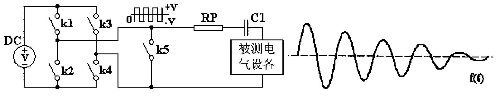
[0056] refer to Figure 5 In this embodiment, the electrical equipment under test is a capacitive load, and the power supply DC includes a three-phase full-bridge controllable rectification circuit composed of rectifier thyristors Q1-Q6, and after the rectification, a filter capacitor C1 is connected, and the H-bridge voltage commutation circuit is continued by the inner band Composed of flow diode IGBT, IGBT drive unit circuit DR1 ~ DR2 is controlled by the single-chip MCU.

[0057] refer to Image 6 , in use, the partial discharge signal coupling sensor CG is connected in series in the circuit of the tested electrical equipment C, and the partial discharge signal output by CG is sent to the input terminal of the MCU of the partial discharge measuring instrument, which is short-circuited with k5 of the MCU port 10-11 The trigger signal is synchronous. This signal controls the partial discharge instrument to collect and record the partial discharge signal when the oscillation...


PUM


Abstract

The invention provides a device for oscillatory wave generation in an electrical device partial discharge test. The device comprises a first switch set, a second switch set, a fifth switch, a power supply, a damping resistor with the adjustable resistance value and an LC oscillating circuit. The first switch set comprises a first switch and a fourth switch. The second switch set comprises a second switch and a third switch. A series circuit composed of the first switch and the second switch, a series circuit composed of the third switch and the fourth switch and the power supply are in parallel connection. A circuit between the first switch and the second switch is connected with one end of the fifth switch. A circuit between the third switch and the fourth switch is connected with the other end of the fifth switch. The LC oscillating circuit and the damping resistor are in series connection and then in parallel connection with the fifth switch. The invention further provided with a method for oscillatory wave generation in the electrical device partial discharge test. High-voltage test oscillatory waves can be generated through the direct-current low-voltage excitation power supply and the electronic switches.

Description

technical field [0001] The invention relates to a device and method for generating an oscillating wave based on direct current excitation, in particular to an oscillating wave generating device and method for partial discharge tests of electrical equipment. Background technique [0002] The basic detection method of the insulation performance of electrical equipment is to measure the sine wave withstand voltage and partial discharge of the electrical equipment. Generally, the method of directly loading the test voltage with the test transformer is used for the test. However, when the equivalent capacitance of the tested product is very large and its test voltage is very high, the capacity of the test transformer to load the test voltage will be very large, resulting in the inability to complete the test on site, making this simple and easy method invalid. A feasible technical solution is to use oscillating waves to conduct sine wave withstand voltage and partial discharge te...

Claims


Application Information

Patent Timeline
IPC IPC(8): G01R31/12G01R1/28
Inventor 张立材王民王燕妮王稚慧陈羽向轩
Owner XI'AN UNIVERSITY OF ARCHITECTURE AND TECHNOLOGY
Why Eureka
Try Eureka