
Method for obtaining radar scattering area

A technology of radar scattering area and radar scattering, which is applied in the field of obtaining radar scattering area and can solve the problem of not being too large.

Active Publication Date: 2013-12-11
NORTHWESTERN POLYTECHNICAL UNIV
View PDF4 Cites 12 Cited by
  • Summary
  • Abstract
  • Description
  • Claims
  • Application Information

AI Technical Summary

Problems solved by technology

In recent years, China has also started the development of complex target RCS and complex environment prediction software, and has achieved some results. However, compared with the international advanced level, there are still gaps in the depth, system, and experimental methods of theoretical research. large gap
[0005] In terms of research on the simulation of radar electromagnetic waves by shooting lines, Elking M D, Roedder M J, Car D D, etc. mentioned the basic theory and RCS evaluation of the ray tracing method in the evaluation of high-frequency radar scattering cross-section analysis capabilities published in IEEE Antenna and Propagation Journal. However, the theoretical method of the ray-tracing method proposed in the evaluation of the high-frequency radar scattering cross-section analysis capability has obvious limitations, which are shown in: 1. The ray-tracing method simulates the radar electromagnetic wave method, in order to accurately reflect the situation of multiple scattering , each surfel in the target model part should not be too large, so that the minimum structure can be well described by the surfel model

Method used


Image

  • Method for obtaining radar scattering area
  • Method for obtaining radar scattering area
  • Method for obtaining radar scattering area

Examples


Embodiment Construction

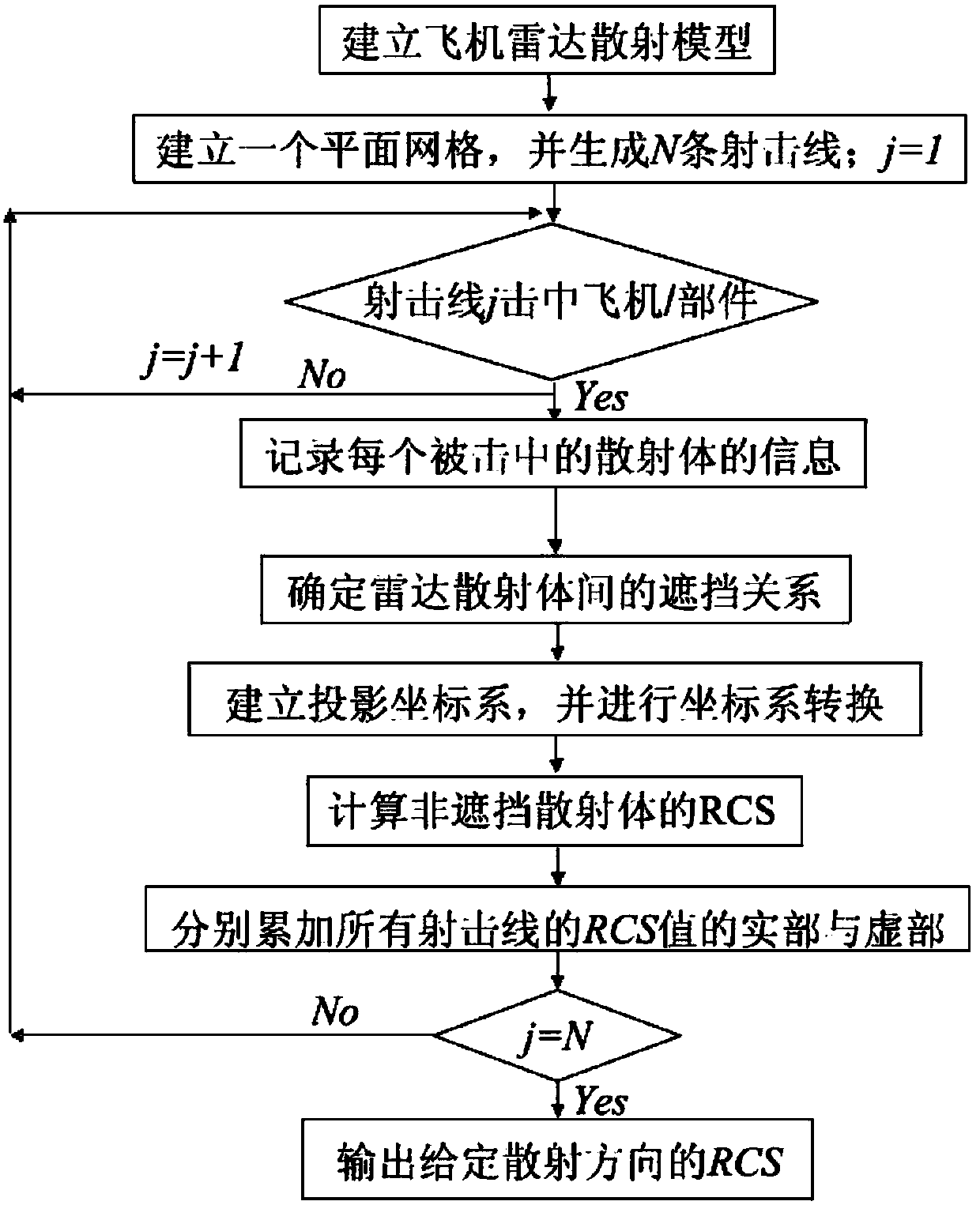
[0044] refer to Figure 1-5 . In this embodiment, a certain type of aircraft is taken as an example to describe in detail the specific steps of the method for obtaining the radar scattering area.

[0045] Step 1: Establish a radar scattering model with the same parameters as the real aircraft. Given radar operating frequency or radar wave wavelength: Use finite element modeling software to establish the original model of the aircraft and its components, and draw the mesh to make the shape of the aircraft and its components approximated by quadrilateral and triangular surface elements. In this embodiment, the given radar wave wavelength λ=0.1m.

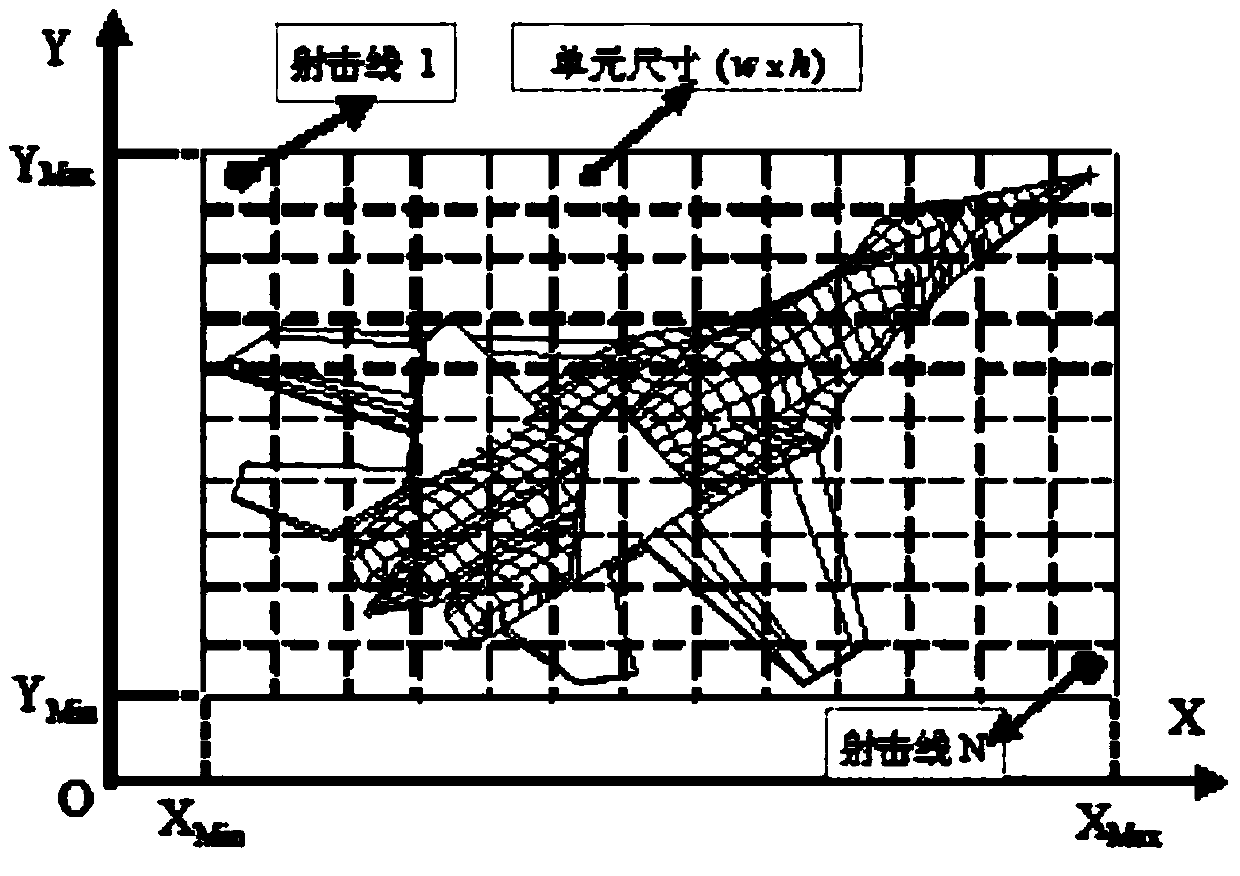
[0046] Step 2: Create a plane grid and generate shooting lines:

[0047] The first step: establish a plane grid and determine the grid step size: select the maximum value X of the X coordinate in the surface element coordinates max and the minimum value X of the X coordinate min , the maximum value Y of the Y coordinate max and the...


PUM


Abstract

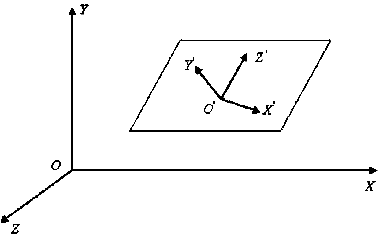
The invention discloses a method for obtaining a radar scattering area. The method is used for resolving the technical problem that an existing method for obtaining the radar scattering area is low in speed. According to the technical scheme, firstly, a radar scattering model is set up, a firing line is used for simulating an attack direction, association attributes of components are defined, and related data of firing line meshes and the like of the components are obtained; secondly, a projected coordinate system is set up, the data are converted into the projected coordinate system, and RCS calculation is carried out on the related data; at last, real parts and imaginary parts are respectively accumulated to obtain the radar scattering area. Due to the fact that the radar scattering area is obtained by means of a physical optical method and a planar firing line method, the planar meshes are laid on a quadrilateral finite element projected model, 1-N firing lines are produced randomly in units of the planar meshes, and surfaces of the components are scanned through the 1-N firing lines to obtain geometric description data of the radar scattering area. Step sizes of the meshes are regulated according to different precision requirements, radar scattering areas of different precisions are obtained, and the speed for obtaining the radar scattering area is increased.

Description

technical field [0001] The invention relates to a method for obtaining radar scattering area. Background technique [0002] The Radar Cross Section (RCS) characteristic of an aircraft is an important technical indicator of the fourth-generation aircraft, so RCS design and calculation is an important link in modern aircraft design. An accurate RCS calculation method can provide great help for the aircraft shape design, it can continuously calculate and change or improve the shape in the aircraft design, and complete the aircraft shape optimization design together with the aircraft aerodynamic design calculation, so that the aircraft can be both It has a good aerodynamic shape and low RCS characteristics. [0003] Due to the safety needs of modern warfare and aviation combat aircraft, sensitivity reduction design has become a very important link in the process of aircraft design. The sensitivity of combat aircraft is an important content of survivability research. At presen...

Claims


Application Information

Patent Timeline
IPC IPC(8): G01S7/41
Inventor 裴扬谢芳敏石帅石蓓宋笔锋
Owner NORTHWESTERN POLYTECHNICAL UNIV
Learn More