A large mode field area all-solid-state optical fiber and its manufacturing method

An all-solid, large mode field technology, applied in cladding fibers, optical waveguides, etc., can solve the problems of high-power laser transmission is not the best, the center of the fiber is easily burned, and the single-mode characteristics of the fiber are destroyed. Achieve the effect of large mode field transmission capacity, increase damage threshold, and increase the degree of overlap

Active Publication Date: 2015-09-23
YANGTZE OPTICAL FIBRE & CABLE CO LTD
View PDF5 Cites 0 Cited by
  • Summary
  • Abstract
  • Description
  • Claims
  • Application Information

AI Technical Summary

Problems solved by technology

Although the refractive index change is small, it still has a negative impact on the mode field, which directly destroys the single-mode characteristic of the fiber
[0010] 2. The bending resistance needs to be further improved
This is ideal for low power laser delivery, but not the best way for high power laser delivery
The energy distribution that is strongly concentrated in the center of the fiber core will make the center of the fiber core more likely to be burned

Method used


Image

  • A large mode field area all-solid-state optical fiber and its manufacturing method
  • A large mode field area all-solid-state optical fiber and its manufacturing method
  • A large mode field area all-solid-state optical fiber and its manufacturing method

Examples


Embodiment Construction

[0042] The content of the present invention will be further described through the embodiments below in conjunction with the accompanying drawings.

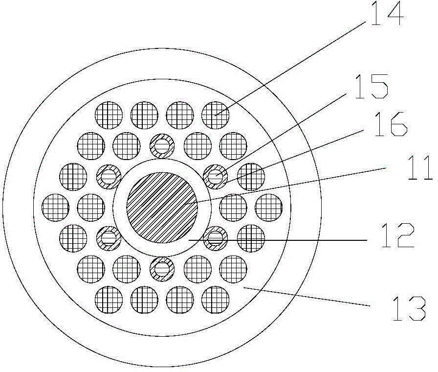
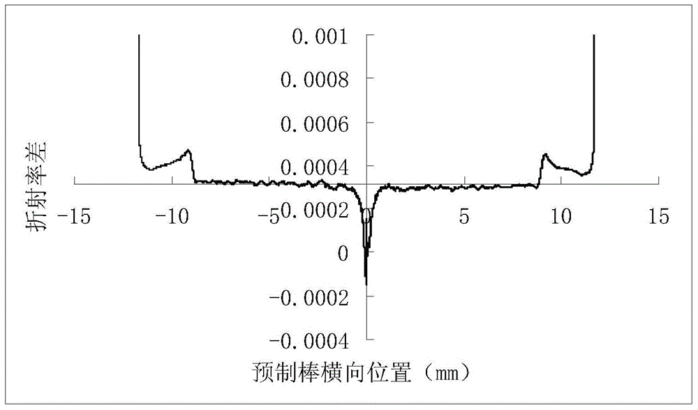
[0043] figure 1 It is a schematic diagram of the basic structure of an embodiment of the present invention. An optical fiber includes a core region and a cladding region. The core area is located in the center of the optical fiber, including the central area 11 and the edge part 12. The material in the central area is made of slightly fluorine-doped quartz glass, and the relative refractive index difference caused by fluorine doping is -0.01% (refers to the refractive index drop ratio), with a diameter of 25 μm; for the refractive index profile see figure 2 , the edge part is silica glass, which is the same material as 13. The cladding region uses pure silica glass as the substrate 13, and contains 2 layers of doping units arranged in periodic close packing, that is, the arrangement is the same as that of the photonic crystal ...


PUM

PropertyMeasurementUnit
diameteraaaaaaaaaa
diameteraaaaaaaaaa

Abstract

The invention relates to a total solid optical fiber with a large-mode field area. The total solid optical fiber comprises a core region and a cladding region, wherein the core region is composed of fluorine-doped quartz glass; the fluorine doping concentration satisfies that the ratio of (n quartz-n fluorine-doped quartz) to n quartz is greater than or equal to 0 and less than 0.05%; the diameter of the core region ranges from 17 microns to 120 microns; the cladding region has pure silicondioxide glass as a substrate, and comprises 2-5 layers of doped units which are periodically arranged in a close stacking way; each doped unit is composed of doped quartz rods, wherein the first layer comprises 6 compound doped quartz rods and 6 fluorine-doped quartz rods; the doped units of the second layer and the layers outside the second layer are all composed of fluorine-doped quartz glass; the pitch Lambda between any two doped quartz rods is equal, and greater than or equal to 3 microns; the outmost layer is a pure quartz glass outer cladding. The manufacturing method provided by the invention employs common push-pull process, and is simple, convenient and feasible. According to the invention, two light guide principles of total internal reflection and photonic bandgap effect are utilized simultaneously to realize the large-mode field area.

Description

technical field [0001] The invention relates to an optical fiber with a large mode field area, in particular to an all-solid microstructure optical fiber with a large mode field area and a manufacturing method thereof, belonging to the technical field of energy transmission optical fibers. technical background [0002] There are two important directions for the development of high-power solid-state lasers: thin-sheet lasers and fiber lasers. The so-called fiber laser is a laser that uses optical fiber as the laser gain medium. For conventional single-mode fiber lasers, the pump light injected into the fiber core must also be single-mode, which limits the efficiency of the pump light into the fiber, resulting in low output power and efficiency of the fiber laser. The proposal of double-clad fiber provides an effective technical way to improve the output power and conversion efficiency of fiber lasers, and changes the history that fiber lasers can only be used as a low-power ...

Claims


Application Information

Patent Timeline
Patent Type & Authority Patents(China)
IPC IPC(8): G02B6/02
Inventor 韦会峰李江陈苏熊良明郭江涛曹蓓蓓
Owner YANGTZE OPTICAL FIBRE & CABLE CO LTD
Why Eureka
Try Eureka