Garbage thermal cracking machine
A technology of pyrolysis and waste, which is applied in special forms of dry distillation, petroleum industry, coke oven, etc. It can solve problems such as difficult continuous operation, difficult recycling of cracked products, and difficult uniform heating of waste.
- Summary
- Abstract
- Description
- Claims
- Application Information
AI Technical Summary
Problems solved by technology
Method used
Image

Examples
Embodiment 1
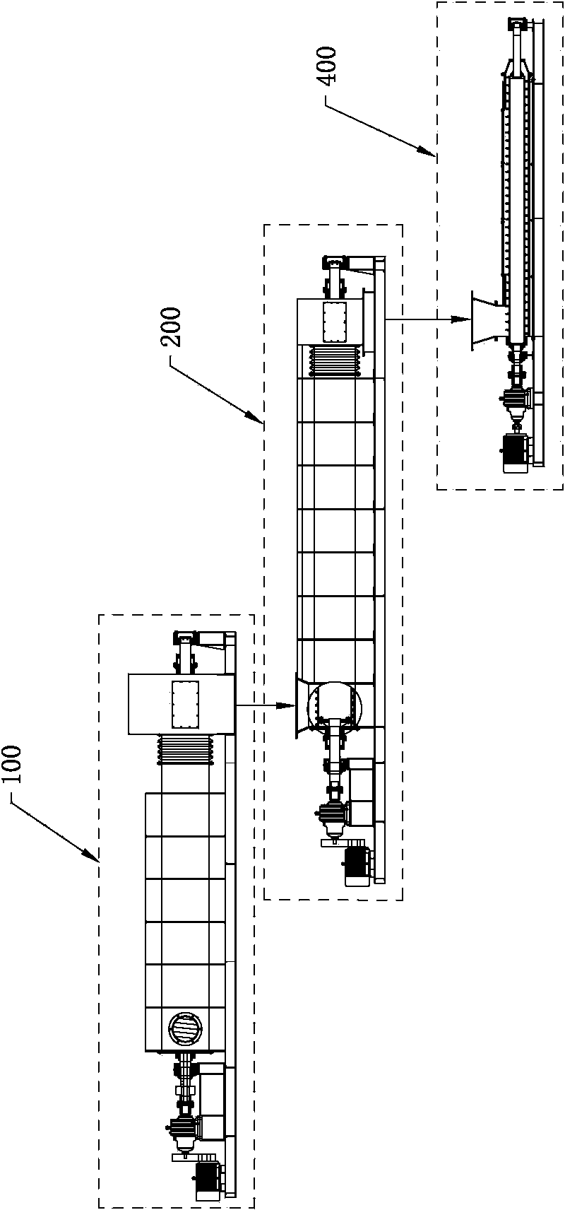
[0038] Such as figure 1 Shown, a kind of rubbish pyrolysis machine comprises feeding device 300, preheating treatment device 100, high temperature cracking device 200 and controller, feeding device 300 is communicated with the feeding end of preheating treatment device 100, and preheating treatment device The discharge end of 100 communicates with the feed end of the pyrolysis device 200 .
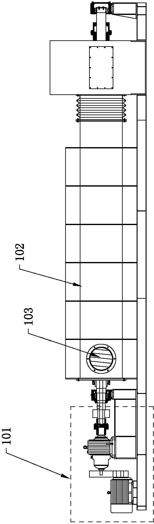
[0039] Such as figure 2As shown, the preheating device 100 of this embodiment includes a first driving device 101, a first screw 103 and a first barrel 102, the first driving device 101 is drivingly connected with the first screw 103, and the first screw 103 is rotatably It is placed inside the first barrel 102, and the material extruded by the first screw 103 is used to seal the material between the first screw 103 and the first barrel 102 from the outside of the feed port, preventing outside air from entering the first material. In the cylinder 102, the purpose of oxygen deficiency in...
Embodiment 2
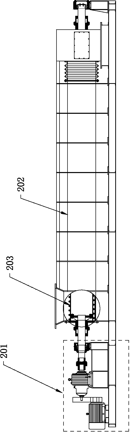
[0043] Such as Figure 4 and 5 As shown, the feeding device 300 of a garbage pyrolysis machine in this embodiment is assembled and communicated with the preheating treatment device 100, and the feeding device 300 includes a feeding cylinder, a third drive device 301 electrically connected to the controller, The third barrel 302 and the third screw 303, the third driving device 301 is connected with one end of the third screw 303, and the other end of the third screw 303 is rotatably inserted inside the third barrel 302, and the third The sealing effect is realized by the material extruded by the third screw 303 between the screw 303 and the third barrel 302 , and the feed barrel is located above the third barrel 302 and communicated with the feed end of the third barrel 302 . Wherein, the central axis of the third screw 303 is perpendicular to the central axis of the first screw 103 , and the third screw 303 is disposed below the first screw 103 .
[0044] In order to ensure...
Embodiment 3
[0047] On the basis of Embodiment 2, a garbage pyrolysis machine of this embodiment also includes a garbage pyrolysis machine and a spray tower for treating acid gas, and the lower part of the spray tower communicates with the cracking zone of the high temperature cracking device 200 . The material is cracked in the pyrolysis device 200 to generate acid gas, combustible gas, tar and coke coal. The air pressure in the pyrolysis device 200 is higher than that in the spray tower. Tower, spray tower removes NO and NO by using alkaline solution such as lime water or alkaline packing 2 , SO 2 、H 2 S, HCl and HCN and other acid gases to obtain clean combustible gases. The structure and principle of the spray tower belong to the prior art and will not be described in detail here.
[0048] The main technical solutions of this embodiment are basically the same as those of Embodiment 1 or Embodiment 2, and the features not explained in this embodiment are explained in Embodiment 1 or ...
PUM
 Abstract
Description
Claims
Application Information
 - R&D
- Intellectual Property
- Life Sciences
- Materials
- Tech Scout
- Unparalleled Data Quality
- Higher Quality Content
- 60% Fewer Hallucinations
Browse by: Latest US Patents, China's latest patents, Technical Efficacy Thesaurus, Application Domain, Technology Topic, Popular Technical Reports.
© 2025 PatSnap. All rights reserved.Legal|Privacy policy|Modern Slavery Act Transparency Statement|Sitemap|About US| Contact US: help@patsnap.com