Water chilling ingot furnace and ingot casting process thereof

A cold casting and water-induced technology, which is applied in the growth of polycrystalline materials, crystal growth, single crystal growth, etc., can solve the problems of reducing the melting speed of silicon materials, the growth rate of crystal growth, the reduction of carrier life, and the increase of carbon impurity content.

Inactive Publication Date: 2013-12-18
TIANWEI NEW ENERGY HLDG
View PDF15 Cites 8 Cited by
  • Summary
  • Abstract
  • Description
  • Claims
  • Application Information

AI Technical Summary

Problems solved by technology

[0005] The purpose of the present invention is to overcome the shortcomings and deficiencies of the above-mentioned prior art, provide a water-cooled ingot casting furnace and its ingot casting process, and solve the problem of using a lifting device to lift and insulate the existing silicon ingot casting furnace when casting silicon ingots. The way of cages to reduce the melting rate of silicon material and control the growth rate of crystals brings the disadvantages of a large number of grain boundaries and dislocations in silicon ingots, and the increase in carbon impurity content leads to the decrease of minority carrier lifetime in silicon materials.

Method used


Image

  • Water chilling ingot furnace and ingot casting process thereof
  • Water chilling ingot furnace and ingot casting process thereof
  • Water chilling ingot furnace and ingot casting process thereof

Examples


Embodiment 1

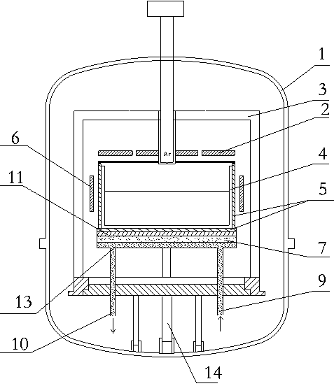
[0021] Such as figure 1 As shown, a water-cooled ingot casting furnace includes a furnace body 1, a heat insulation cage 3 arranged in the furnace body, and a heat exchange platform 11 arranged in the heat insulation cage 3, and a Crucible 4, heaters are distributed on and around the top of the crucible 4, a bottom heater 7 is provided at the lower end of the heat exchange platform 11, and a water cooling plate 13 is provided at the lower end of the heat exchange platform 11, and the water cooling plate 13 is located at At the lower end of the bottom heater 7, a flow cavity is arranged in the water cooling plate 13, and a water inlet 9 and a water outlet 10 are arranged. The water inlet 9 and the water outlet 10 are connected through the flow cavity, and the water inlet 9 and the water outlet 10 are also connected to the furnace body 1 respectively. outer end. This device reduces the temperature at the bottom of the crucible 4 by passing cold water into the water cooling plat...

Embodiment 2

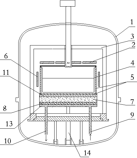
[0036] Such as figure 2 , the structure of this embodiment is basically the same as that of Embodiment 1, the difference is that an adiabatic solidified felt 8 is arranged between the water cooling plate 13 and the bottom heater 7, and the adiabatic solidified felt 8 can effectively block the downward transfer of heat and reduce energy consumption , to ensure the heating effect of the bottom heater 7.

Embodiment 3

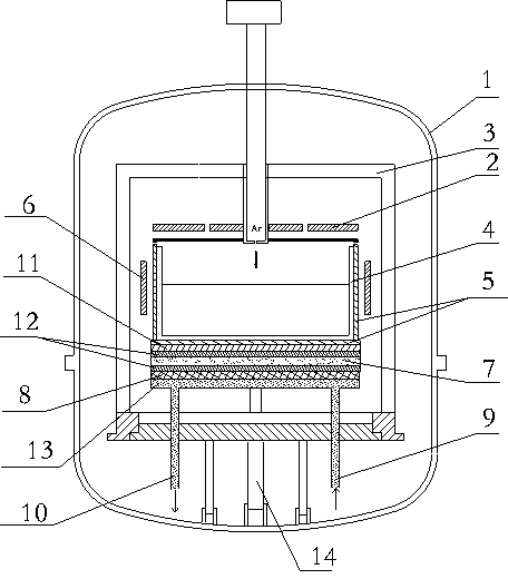
[0038] Such as image 3 , the structure of this embodiment is basically the same as that of Embodiment 2, the difference is that the upper and lower sides of the bottom heater 7 are covered with a layer of cubic boron nitride 12, and the cubic boron nitride 12 is an insulator with good thermal conductivity, which can not only effectively prevent The graphite bottom heater 7 forms a circuit with the graphite exchange platform 3, which can also ensure effective and uniform transfer of heat.


PUM


Abstract

The invention discloses a water chilling ingot furnace and an ingot casting process thereof. A water cooling disc (13) is arranged at the lower end of a heat exchange table (11), located at the lower end of a bottom heater (7), internally provided with a flow cavity and provided with a water inlet (9) and a water outlet (10), wherein the water inlet (9) and the water outlet (10) are communicated through the flow cavity, and are respectively communicated with the outer end of a furnace body (1). The water chilling ingot furnace disclosed by the invention has the beneficial effects that the problem of influence on formation of columnar crystals due to transfer of heat of a crucible in a radial direction caused by lifting an insulating cage to dissipate heat from a side is solved by way of replacing the original mode of lifting the insulating cage to dissipate heat by water cooling; an insulating cage body in a lifting process is prevented from rubbing with the top of the insulating cage to generate carbon dust which is easy to enter the crucible to increase carbon impurity content of a silicon ingot so as to cause lattice deformation.

Description

technical field [0001] The invention relates to a polysilicon ingot casting furnace, in particular to a water-cooled ingot casting furnace and an ingot casting process thereof. Background technique [0002] Polysilicon ingot furnace is the main equipment for polysilicon production in the field of photovoltaics. Its working process is to place dopant and polysilicon material in a vacuum and high temperature state, and then add an inert protective gas. After heating, melting, directional crystallization, annealing and cooling for several After a stage, it grows into a polycrystalline silicon ingot with a certain crystal growth direction. [0003] In the existing ingot casting process, the top and side heaters are used to control the thermal field distribution, and a lifting device is used to lift the heat insulation cage during the melting and crystal growth stage to reduce the melting speed of silicon material and control the crystal growth speed, annealing In the second sta...

Claims


Application Information

Patent Timeline
Patent Type & Authority Applications(China)
IPC IPC(8): C30B28/06C30B29/06
Inventor 林洪峰李书森冯媛刘兴翀兰洵龙巍赵秀生
Owner TIANWEI NEW ENERGY HLDG
Why Eureka
Try Eureka