Quantitative control valve of fuel gas entering cylinder on gas engine

A gas engine, quantitative control technology, applied in the direction of engine components, combustion engines, machines/engines, etc., can solve the problems of engine output power limitation, high gas consumption rate, poor dynamic response of gas volume adjustment, etc., to eliminate backfire and deflagration low risk, low gas consumption rate and good dynamic response

Active Publication Date: 2013-12-18
GUANGZHOU DIESEL ENGINE FACTORY
View PDF5 Cites 9 Cited by
  • Summary
  • Abstract
  • Description
  • Claims
  • Application Information

AI Technical Summary

Problems solved by technology

[0004] Yet the defective of above-mentioned air intake and gas supply system is:
[0005] (1) It cannot be applied to gas with fast combustion speed and large ignition range. This is because when the engine is working, the entire intake pipe is filled with combustible gas mixture, so for gas containing hydrogen and carbon monoxide gas with large ignition range and fast combustion speed, its The tendency and danger of tempering are serious, so the safety is poor;
[0006] (2) The advantages of the supercharged model cannot be fully utilized, because the entire intake pipe is full of combustible gas, so the valve overlap angle of the non-supercharged model can only be used to avoid combustible gas directly escaping from the exhaust pipe during scavenging, so increasing The gas engine with high pressure has to adopt non-supercharged valve overlap angle, resulting in high exhaust temperature, low strengthening degree, low thermal efficiency, high gas consumption rate, and the output power of the engine is greatly limited;
[0007] (3) The pipeline before the gas enters the cylinder is long, and the dynamic response of gas volume adjustment is poor
However, the gas control of the existing gas engine is quantitative control of the whole machine, and the quantitative control valve is a pipe throttling butterfly valve with poor adjustment accuracy, which is only suitable for the gas flow regulation with large pipe size, extremely low pressure and large flow rate. It cannot meet the requirements of cylinder-by-cylinder gas quantitative control with less flow rate, higher pressure and high adjustment accuracy
Although some existing gas flow control valves can meet the requirements of cylinder-by-cylinder gas quantitative control, they must be automatically controlled according to the working conditions of the cylinders, such as engine starting, speed regulation, load distribution of each cylinder, and shutdown. Adjusting the gas flow rate, so that the existing gas flow control valve is still difficult to meet the requirements for automatic control and adjustment of the above-mentioned engine working state, so the existing gas flow control valve cannot be directly applied to the gas supply system

Method used


Image

  • Quantitative control valve of fuel gas entering cylinder on gas engine
  • Quantitative control valve of fuel gas entering cylinder on gas engine
  • Quantitative control valve of fuel gas entering cylinder on gas engine

Examples


Embodiment 1

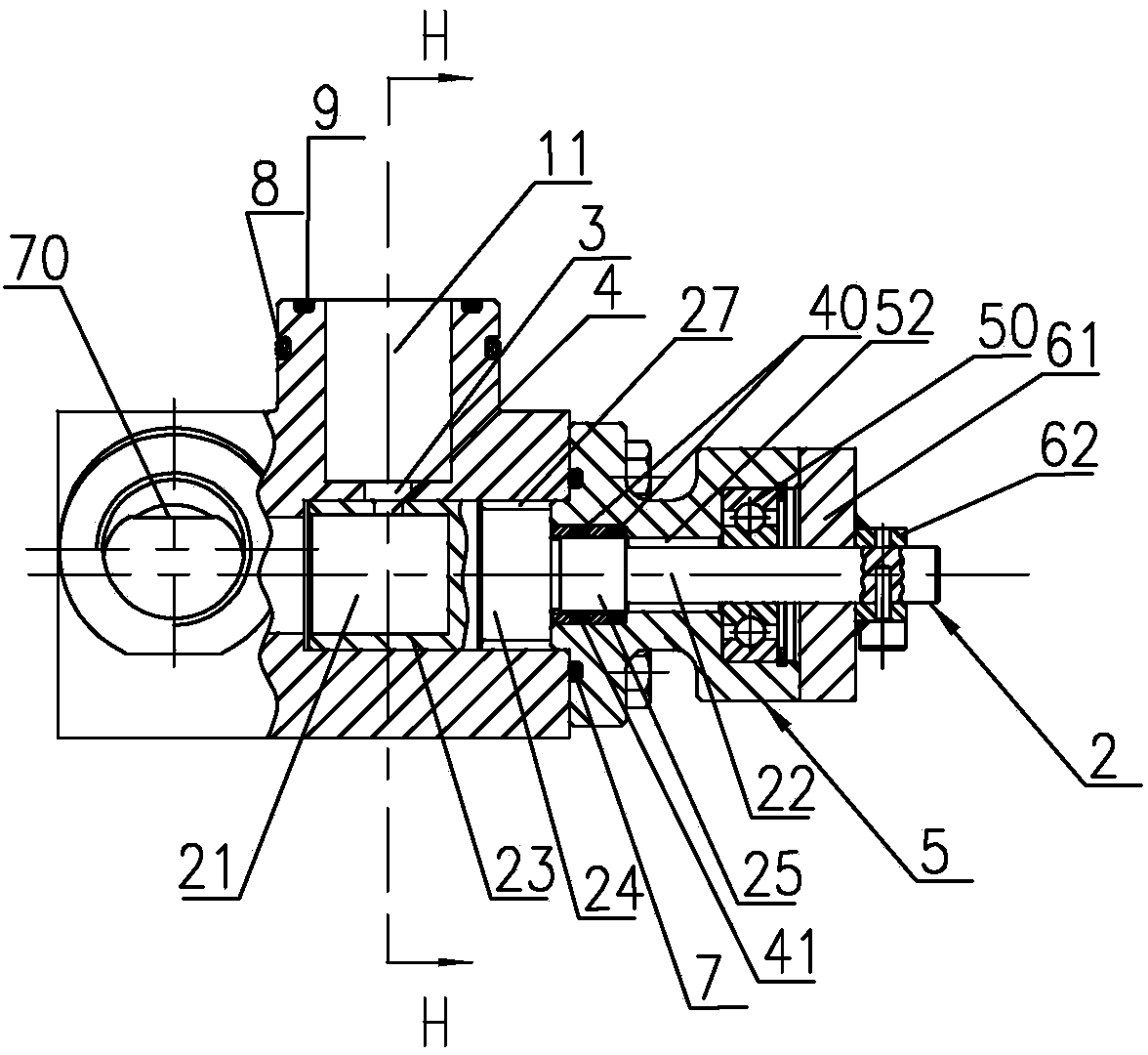
[0041] Such as Figure 3-12 Shown is a gas engine gas cylinder quantitative control valve 18 of the present invention, which includes a valve body 1, a valve stem 2 and a valve handle 6 installed in the valve body 1, and the valve body 1 is an elongated block body. The valve body 1 is provided with an air inlet hole and an air outlet hole whose centerlines are perpendicular to each other. An air outlet hole 11 is provided, and one end of the air inlet hole 11 is an air intake end for connecting gas, and the other end is set on one end surface of the valve body 1 as an adjustment end for inserting the valve stem 2, and the air outlet hole 11 is located at On the wall of the valve body close to the adjustment end of the air inlet passage, the inner port of the air outlet passage 11 communicates with the air intake passage to form the outer port 3 for adjustment, and the outer port of the air outlet passage 11 is used to connect with the engine cylinder; the front end 23 of the val...

Embodiment 2

[0049] Such as Figure 13 As shown, the difference between this embodiment and Embodiment 1 is that a valve seat 45 is added at the regulating end of the valve body 1, which is formed by the flange cover of Embodiment 1 corresponding to the gap between the inner and outer ends of the shaft hole. The elongated valve seat 45 formed by partial extension.

[0050] In other embodiments, the central lines of the air inlet hole and the air outlet hole in the valve body may cross each other.


PUM


Abstract

The invention discloses a quantitative control valve of fuel gas entering a cylinder on a gas engine. The quantitative control valve comprises a valve body and a valve rod arranged in the valve body, wherein the valve body is internally provided with a gas inlet channel and a gas outlet channel, and the central lines of the gas inlet channel and the gas outlet channel are mutually crossed or vertical; one end of the gas inlet channel is the gas inlet end, and the other end of the gas inlet channel is arranged on one end surface of the valve body and is an adjusting end; the gas outlet channel is positioned on a valve body wall close to the adjusting end of the gas inlet channel; an inner port of the gas outlet channel is communicated with the gas inlet channel to form an adjusting outer hole; the front end part of the valve rod is barrel-shaped, is inserted into the gas inlet channel from the adjusting end of the gas inlet channel and can rotate in the gas inlet channel; the rear end part of the valve rod extends out of the valve body to be connected with a load controller; a gas chamber communicated with the gas inlet port is formed at the front end part of the valve rod; the peripheral wall of the gas chamber of the valve rod is provided with a through hole as an adjusting inner hole; the adjusting inner hole and the adjusting outer hole correspond in the axial position of the valve rod; the adjusting inner hole can change between states of complete coincidence with the adjusting outer hole and complete staggering with the adjusting outer hole along with rotation of the valve rod to adjust the entering amount of the fuel gas.

Description

technical field [0001] The invention relates to an air intake and fuel supply system of a gas engine, in particular to a gas engine cylinder quantitative control valve. Background technique [0002] The work of the gas engine is achieved by mixing gas and air in a certain proportion by the electrical system and then sending them into the engine cylinder to burn and do work. Gas and air mixing generally takes place upstream of the engine intake manifold. [0003] Such as figure 1 As shown, the existing air intake and gas supply systems usually adopt the mixer pre-mixing type, which is characterized in that both gas and air are mixed in the mixer 14 to obtain a mixed gas E that maintains a basically stable air-fuel ratio, and then enters the engine through the engine. The gas main pipe 15 and the intake branch pipe 16 of each cylinder 17 enter each cylinder. The performance of the mixer equipped with the engine directly affects the performance index of the engine. The advant...

Claims


Application Information

Patent Timeline
Patent Type & Authority Applications(China)
IPC IPC(8): F16K3/26F16K3/30F16K27/04F16K31/44F16K37/00F02M21/02
CPCY02T10/30
Inventor 张巧亮冯盛宝林国锋廖林德李文聪朱涛
Owner GUANGZHOU DIESEL ENGINE FACTORY
Why Eureka
Try Eureka