Body temperature monitoring device with timed awakening, identity recognition and data remote wireless transmission functions
A technology for identification and monitoring devices, which can be used in electrical digital data processing, special data processing applications, record carriers used by machines, etc., and can solve problems such as increasing workload.
- Summary
- Abstract
- Description
- Claims
- Application Information
AI Technical Summary
Problems solved by technology
Method used
Image
Examples
Embodiment 1
[0035] Embodiment 1: Preparation of body temperature monitoring probe (A)
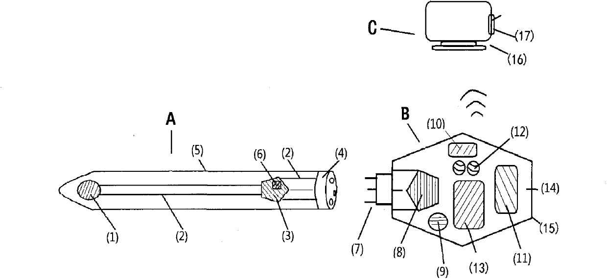
[0036] According to attached figure 2 As shown in the structure, a thermistor is selected as the body temperature sensing element (1) as an example to further illustrate the preparation of the body temperature monitoring probe of the present invention.
[0037] 1. Select an NTC thermistor specially used for electronic thermometers as the body temperature sensing element (1), the resistance value exchange accuracy can reach ±1‰, and a body temperature probe suction cup (19) made of silica gel on the outside completely seals the body temperature sensing element (1) Sealed inside, the body temperature probe suction cup (19) can be easily adsorbed on the body surface during use.
[0038] 2. The thermistor is connected with the data processor and the identification chip (18) with a soft conducting wire (2). The scheme selected in this embodiment is to connect the data processor (3) and the identification ...
Embodiment 2
[0042] Embodiment 2: Preparation of body temperature monitoring device host (B)
[0043] According to attached image 3 The structure is shown in the attached Figure 4 The circuit design further illustrates the preparation of the host (B) of the body temperature monitoring device of the present invention.
[0044] attached Figure 4 As shown in the circuit design, the corresponding codes of each component in the circuit design schematic diagram are: CPU-single-chip microcomputer (8), USB-USB communication interface (21), RF-wireless communication module (10), LCD-display ( 11), SB-control button (12), BP-electronic prompter (22), PW-power supply (13).
[0045] Wherein: the single-chip microcomputer (8) adopts AT89C51, the wireless communication module (10) adopts nRF401, the power supply (13) adopts a 6V rechargeable lithium battery, and other parts adopt conventional electronic components. Figure 4 The circuit design requires assembly and testing.
[0046] The working ...
Embodiment 3
[0048] Embodiment 3: the preparation mode and working mode that the real-time clock chip (23) is arranged on the data processing terminal (C)
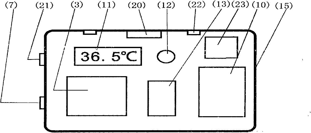
[0049] According to attached Figure 5 The structure is shown in the attached Figure 6 The circuit design further illustrates the preparation of the data processing terminal (C) of the present invention.
[0050] attached Figure 6 As shown in the circuit design, the corresponding codes of each component in the circuit design schematic diagram are: CPU-single-chip microcomputer (8), EEPROM-storage module (24), RTCC-real-time clock chip (23), USB-USB communication interface (21), RF-wireless communication module (10), LED-display (11), SB-control button (12), BP-electronic prompter (22), PW-power supply (13), BT-AC110V external power supply port (20).
[0051] Wherein: the single-chip microcomputer (8) adopts AT89C51, the real-time clock chip adopts RTC-4574SA, the wireless communication module (10) adopts nRF401, the power supply ...
PUM
 Abstract
Description
Claims
Application Information
 - R&D
- Intellectual Property
- Life Sciences
- Materials
- Tech Scout
- Unparalleled Data Quality
- Higher Quality Content
- 60% Fewer Hallucinations
Browse by: Latest US Patents, China's latest patents, Technical Efficacy Thesaurus, Application Domain, Technology Topic, Popular Technical Reports.
© 2025 PatSnap. All rights reserved.Legal|Privacy policy|Modern Slavery Act Transparency Statement|Sitemap|About US| Contact US: help@patsnap.com


