Coal tar filtering device and method

A filtering device and technology for coal tar, applied in the field of coal chemical industry, can solve the problems of easy blocking of filter elements, high frequency of backflushing, low filtering efficiency, etc., and achieve the effects of reducing the amount of dirty oil, stable operation of equipment and simple filtering method.

Active Publication Date: 2013-12-25
SHENMUFUYOU ENERGY TECH
View PDF6 Cites 3 Cited by
  • Summary
  • Abstract
  • Description
  • Claims
  • Application Information

AI Technical Summary

Problems solved by technology

[0003] Tubular backwash filter A row of tubular filters is formed side by side, and the filtered filtrate is used for backflushing in chronological order. The frequency of backflushing is high, resulting in more dirty oil, and the filtration efficiency is low; the tank type automatic backwash filter One opening and one preparation, nitrogen or steam explosion back blowing, oil is used to take out impurities during back flushing, and the oil content in dirty oil is high; cross-flow automatic back blowing system, after back blowing, the pre-filter oil is used to take out impurities, Low blowback efficiency
[0004] The above automatic backflushing filter devices are used for coal tar filtration. Since coal tar contains a large amount of viscous components such as colloids and asphaltenes, the pressure difference rises rapidly and cannot be recovered by backflushing, and the yield of coal tar is low. Especially for the coal tar hydrogenation process, the filtration accuracy is high, the filter element is easily blocked, and it cannot run stably for a long period of time

Method used


Image

  • Coal tar filtering device and method
  • Coal tar filtering device and method
  • Coal tar filtering device and method

Examples


Embodiment 1

[0033] The coal tar filtering device of this embodiment is composed of 10 canister filters connected in parallel, and one canister filter communicates with an adjacent canister filter through a pipeline.

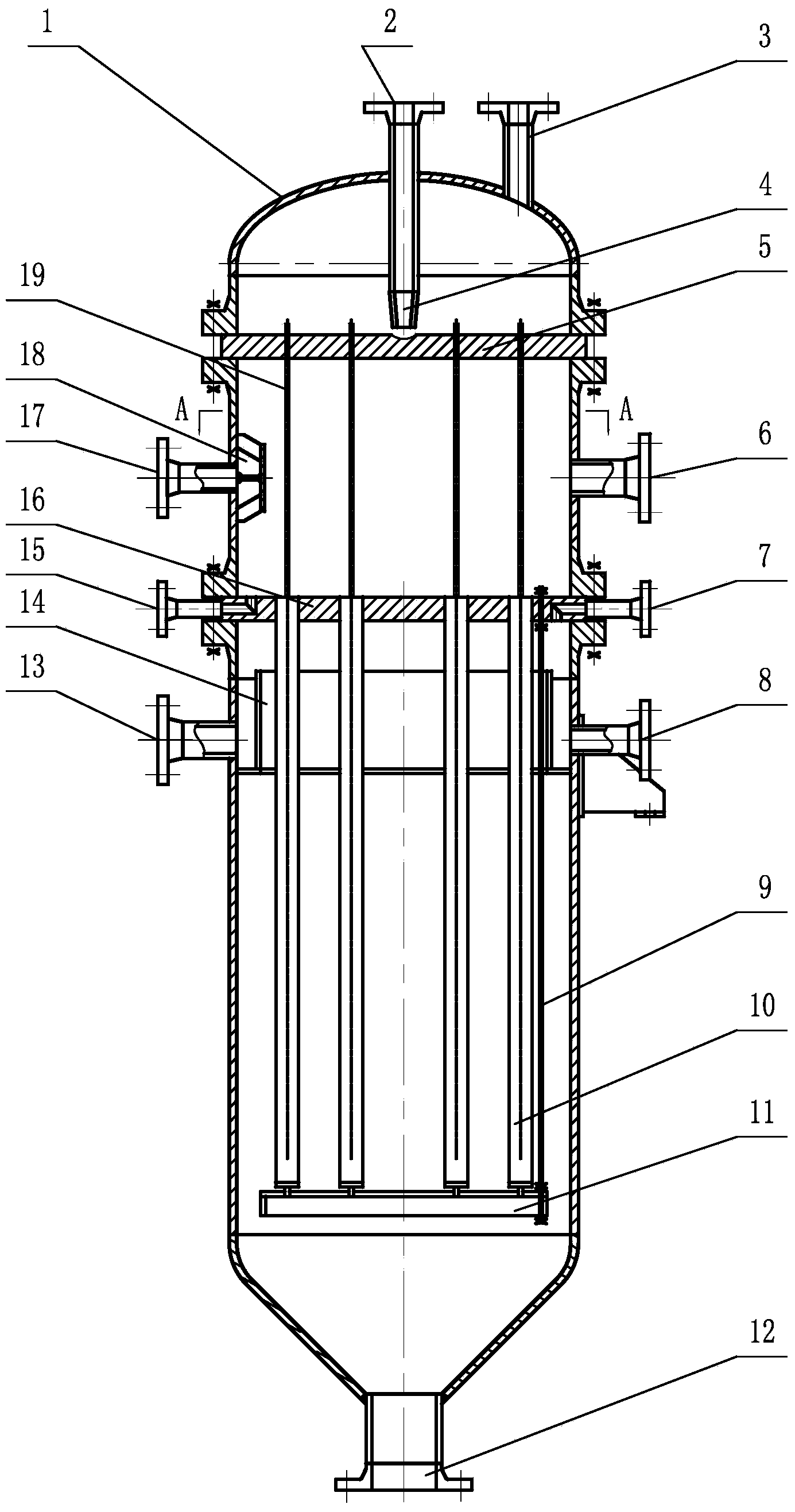
[0034] The construction of each canister filter see figure 1 , consisting of a tank body 1 and a filtered residual oil collection chamber, a filtrate collection chamber and a filter chamber distributed in the inner cavity of the tank body 1 from top to bottom. The top of the tank body 1 in this embodiment is processed with a residual oil outlet and a safety valve interface, and the bottom is funnel-shaped. A safety valve 3 is installed on the safety valve interface. A sewage outlet is processed at the bottom of the tank body 1, and a sewage discharge valve is installed on the sewage outlet. 12. Control the discharge of residue through the blowdown valve 12 switch.

[0035] The residual oil collection chamber after filtration in this embodiment is in the upper section of the...

Embodiment 2

[0048] In this embodiment, the coal tar filtering device is composed of 8 canister filters connected in parallel, and one canister filter communicates with an adjacent canister filter through a pipeline.

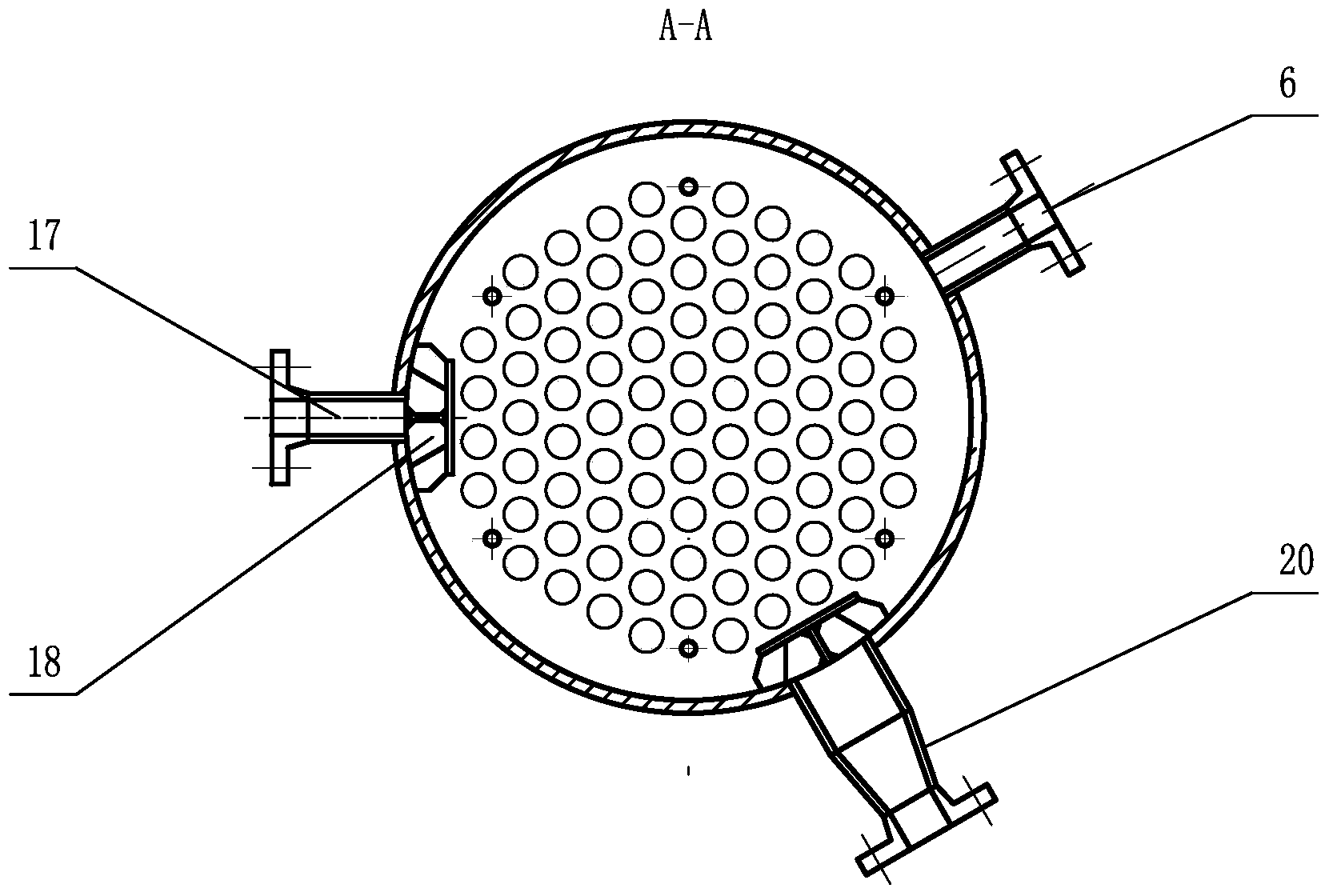
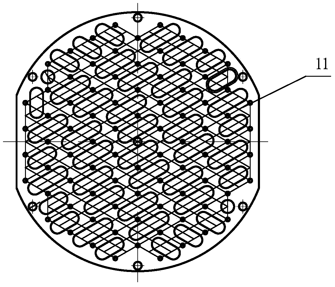
[0049] In the tank filter of this embodiment, 60 filter elements 10 are installed between the filter element upper fixing plate 16 and the filter element lower fixing plate 11, and the upper and lower ends of the filter element 10 are respectively fixed in the upper filter element fixing hole and the filter element lower fixing hole by nuts , the filter element 10 of the present embodiment adopts a Johnson filter element, and its filtration accuracy reaches 15 μm, and is distributed in an equilateral triangle in the filter chamber, and the distance between one filter element 10 and an adjacent filter element 10 is 90 mm.

[0050] Other components and their connections are the same as those in Embodiment 1.

[0051] The method that coal tar is filtered with above-mentioned fi...

Embodiment 3

[0053] In this embodiment, the coal tar filtering device is composed of 16 canister filters connected in parallel, and one canister filter communicates with an adjacent canister filter through a pipeline.

[0054] In the tank filter of this embodiment, 90 filter elements 10 are installed between the filter element upper fixing plate 16 and the filter element lower fixing plate 11, and the upper and lower ends of the filter element 10 are respectively screwed into the upper filter element fixing hole and the filter element lower fixing hole. , the filter element 10 of the present embodiment adopts a Johnson filter element, and its filtration accuracy reaches 1 μm, and is distributed in an equilateral triangle in the filter chamber, and the distance between one filter element 10 and an adjacent filter element 10 is 60 mm.

[0055] Other components and their connections are the same as those in Embodiment 1.

[0056] The method that coal tar is filtered with above-mentioned filte...


PUM


Abstract

The invention relates to a coal tar filtering device and method. The device comprises at least one can-type filter, wherein the can-type filter is internally divided into an after-filtration residual oil collecting chamber, a filter liquor collecting chamber and a filtering chamber from top to bottom; a residual oil leading-out tube plate is arranged between the after-filtration residual oil collecting chamber and the filter liquor collecting chamber; a residual oil leading-out tube is arranged above the residual oil leading-out tube plate, an after-filtration residual oil guide tube is arranged in the filter liquor collecting chamber, an upper filter element fixing plate is arranged between the filter liquor collecting chamber and the filtering chamber, and filter elements and a raw oil distributor as well as a lower filter element fixing plate are arranged in the filtering chamber; the lower filter element fixing plate is connected with the upper filter element fixing plate by a connecting rod, and the upper and lower ends of the filter elements are fixed on the upper filter element fixing plate and the lower filter element fixing plate respectively. According to the invention, the sump oil quantity can be greatly reduced, the filtering precision of the device is improved, the equipment runs stably, the filtering method is relatively simple, the coal tar recovery rate is high, environmental pollution is less, the filtering efficiency is high, and the coal tar filtering device and method are suitable for industrialized application.

Description

technical field [0001] The invention belongs to the technical field of coal chemical industry, and in particular relates to a filter device and method for pretreatment of coal tar. Background technique [0002] Coal tar needs to be pretreated during processing to remove mechanical impurities, and filtration is one of the commonly used methods. According to different processes, it can be divided into: tubular automatic backflush filter, tank type automatic backflush filter, and cross-flow backflush filter. [0003] Tubular backwash filter A row of tubular filters is formed side by side, and the filtered filtrate is used for backflushing in chronological order. The frequency of backflushing is high, resulting in more dirty oil, and the filtration efficiency is low; the tank type automatic backwash filter One opening and one preparation, nitrogen or steam explosion back blowing, oil is used to take out impurities during back flushing, and the oil content in dirty oil is high; ...

Claims


Application Information

Patent Timeline
Patent Type & Authority Applications(China)
IPC IPC(8): B01D36/00
Inventor 杨占彪王树宽于广彦
Owner SHENMUFUYOU ENERGY TECH
Why Eureka
Try Eureka