Hydraulic gas vacuum pump

A vacuum pump and gas technology, applied in liquid variable volume machinery, pumps, piston pumps, etc., can solve problems such as difficulty in meeting different needs, high failure rate, easy wear and tear, reducing volume and weight, large pressure margin, The effect of fewer parts

Inactive Publication Date: 2013-12-25
天津市海雅实业有限公司
View PDF6 Cites 5 Cited by
  • Summary
  • Abstract
  • Description
  • Claims
  • Application Information

AI Technical Summary

Problems solved by technology

Metal sealing rings are mostly used for sealing rings, which are easy to wear, high energy consumption, and high failure rate
Moreover, the cylinder body of the hydraulic cylinder is generally a box-type structure, and the pressure output can only be adjusted in steps, which is difficult to meet the different needs of the market.

Method used


Image

  • Hydraulic gas vacuum pump

Examples


Embodiment Construction

[0024] The hydraulic gas vacuum pump of the present invention will be further described below in conjunction with the accompanying drawings and specific embodiments. In the accompanying drawings, the same components as those in the prior art are designated with the same reference numerals. The following examples are only used to illustrate the present invention but not to limit the present invention.

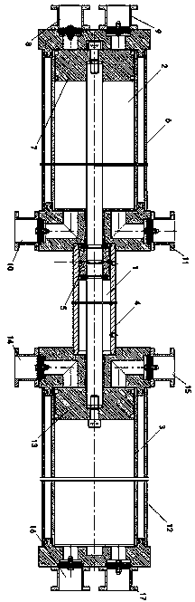
[0025] figure 1 It is a structural schematic diagram of the hydraulic gas vacuum pump of the present invention. like figure 1 As shown, the hydraulic gas vacuum pump of the present invention includes a cylinder part 1 for driving hydraulic oil in the middle, and a left compression cylinder part 2 and a right compression cylinder part 3 connected to both ends of the cylinder part 1 .

[0026] The cylinder portion 1 includes a cylinder barrel 4 and a cylinder piston 5 disposed inside the cylinder barrel 4 . The hydraulic cylinder part 1 adopts a hydraulic control method, and th...


PUM


Abstract

The invention discloses a hydraulic gas vacuum pump. The vacuum pump comprises an oil cylinder part, a left compression cylinder part and a right compression cylinder part, wherein the oil cylinder part for driving hydraulic oil is arranged in the middle of the hydraulic gas vacuum pump, and the left compression cylinder part and the right compression cylinder part are connected at the two ends of the oil cylinder part; the oil cylinder part comprises an oil cylinder barrel and an oil cylinder piston in the oil cylinder barrel; each compression cylinder part comprises a compression cylinder barrel and a compression cylinder piston, and the two ends of each compression cylinder barrel are provided with an air suction valve and a vent valve. The compression cylinder pistons and the oil cylinder piston are connected on the same piston rod. The hydraulic oil cylinder part adopts a hydraulic control way and performs commutation control by a hydraulic control reciprocating machine, so that the reciprocating motion of the hydraulic oil cylinder can be realized. According to the hydraulic gas vacuum pump, the pistons are directly driven to move through hydraulic oil driving so as to realize the low-jig-frequency and long-stroke motion of the pistons, so that the service life is long, the trouble is little and the maintenance cost is low. The gas vacuum pump is simple in structure, few in parts, small in size and light in weight. Compared with a traditional mechanical drive triplex pump, the number of the parts of the hydraulic gas vacuum pump is reduced by 65%, and the size and weight is reduced by more than 60%.

Description

technical field [0001] The invention relates to a vacuum pump, in particular to a hydraulic gas vacuum pump. Background technique [0002] Vacuum pumps include water ring pumps, reciprocating pumps, slide valve pumps, rotary vane pumps, Roots pumps and diffusion pumps, etc., and are widely used in metallurgy, chemical industry, food, electronic coating and other industries. At present, these pumps are indispensable main pumps in the application of vacuum technology in various industries of our country's national economy. Most of the current vacuum pumps use a crank-link mechanism, which converts the rotary motion into a linear motion through the link mechanism, so that the piston moves up and down to generate compression. During the compression process, the piston has a fast speed and a short stroke. Most of the sealing rings are metal sealing rings, which are easy to wear, have high energy consumption and high failure rate. Moreover, the cylinder body of the hydraulic cyl...

Claims


Application Information

Patent Timeline
Patent Type & Authority Applications(China)
IPC IPC(8): F04B37/14F04B35/02
Inventor 刘莹
Owner 天津市海雅实业有限公司
Why Eureka
Try Eureka