
Low power consumption injection locked frequency tripler
An injection locking and frequency tripler technology, applied in power oscillators, electrical components, etc., can solve the problem of circuit limitation and wide application, and achieve the effect of increasing the output frequency locking range, low DC power consumption, and low power consumption
- Summary
- Abstract
- Description
- Claims
- Application Information
AI Technical Summary
Problems solved by technology
Method used
Image

Examples
Embodiment Construction
[0019] Describe below in conjunction with accompanying drawing:
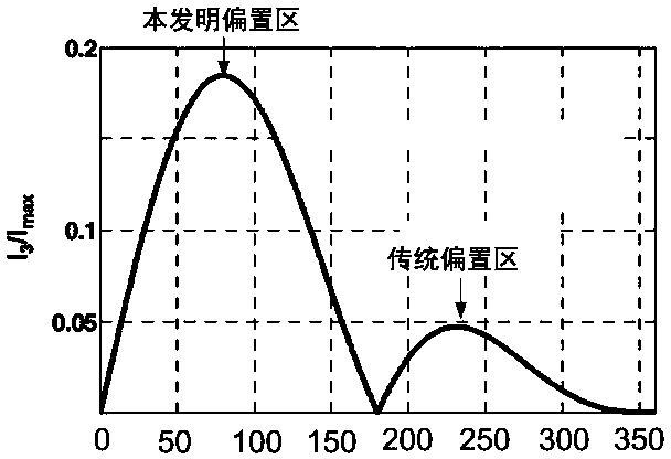
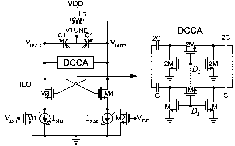
[0020] Such as figure 1 As shown, the traditional injection-locked tripler circuit consists of L1 and C1 to form a resonant cavity, and cross-coupling tubes M3 and M4 provide negative resistance to maintain oscillation. The signal is input to the gates of the injection transistors M1 and M2 through the off-chip balun, and the third harmonic generated by the transistors M1 and M2 is injected into the resonant cavity through the sources of M3 and M4. At the same time, the transistors M1 and M2 also provide a DC bias for the circuit, so that the entire circuit can start to oscillate normally. figure 2 The efficiency of third harmonic current generation for transistors M1 and M2 as a function of conduction angle. Obviously, in order to obtain a larger third harmonic current and a larger locking range, transistors M1 and M2 should be biased in the weak inversion region ( conduction angle 50~100 degrees). However...
PUM
 Abstract
Description
Claims
Application Information