Audio signal circuit

An audio signal and circuit technology, which is applied in the field of audio signal circuits, can solve the problems of inconvenient low-power system application, high power consumption, and complicated circuits, and achieve the effects of improving stability, less clutter, and simple circuit structure

Inactive Publication Date: 2013-12-25
昆山龙仕达电子材料有限公司
View PDF4 Cites 2 Cited by
  • Summary
  • Abstract
  • Description
  • Claims
  • Application Information

AI Technical Summary

Problems solved by technology

However, its circuit is complex and consumes a lot of power, which is not convenient for low-power system applications.

Method used


Image

  • Audio signal circuit

Examples


Embodiment Construction

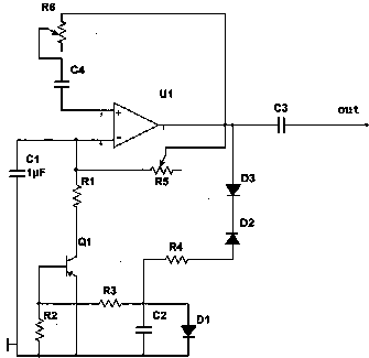
[0012] Such as figure 1 As shown, the present invention includes an operational amplifier, a triode, a variable resistor, a resistor, a capacitor and a diode. The inverting input terminal of the operational amplifier U1 is connected to the collector of the transistor Q1 through the first resistor R1, and the base of the transistor Q1 is connected through the second resistor R1. The resistor R2 is grounded, and its emitter is grounded. The inverting input terminal of the operational amplifier U1 is connected to one end of the first variable resistor R5, and the adjustment terminal of the first variable resistor R5 is connected to the output terminal of the operational amplifier U1. The operational amplifier U1 The output terminal of the second variable resistor R6 is connected to one end of the second variable resistor R6, and the adjustment terminal of the second variable resistor R6 is connected to the non-inverting input terminal of the operational amplifier U1 through the fo...


PUM


Abstract

The invention discloses an audio signal circuit which comprises an operational amplifier, a triode, a variable resistor, a resistor, a capacitor and a diode. The audio signal circuit uses the triode which works in a variable resistance area to form stable nonlinear resistance output and can maintain constant output voltage by adjusting the variable resistor in the circuit and adjusting the strength of feedback. Furthermore, the problem of improving the stability of output voltage amplitude is solved. The audio signal circuit is simple in structure, stable in signal output, little in clutter and suitable for small-power electronic systems.

Description

[0001] technical field [0002] The invention relates to a signal source circuit, in particular to an audio signal circuit. Background technique [0003] The signal source circuit is the core unit circuit of an analog integrated circuit, especially in power management chips, the signal source often determines the performance indicators of such chips, and it is widely used in various analog circuits such as oscillators, phase-locked loops, and data converters. and digital-analog hybrid integrated circuits. However, its circuit is complex and consumes a lot of power, which is not convenient for low-power system applications. [0004] Therefore need a kind of new technical scheme to solve the above problem. Contents of the invention [0005] Purpose of the invention: In view of the problems and deficiencies in the above-mentioned prior art, the purpose of the invention is to provide an audio signal circuit whose signal generation is stable. [0006] Technical solution: The...

Claims


Application Information

Patent Timeline
Patent Type & Authority Applications(China)
IPC IPC(8): H04R3/00
Inventor 王火明
Owner 昆山龙仕达电子材料有限公司
Why Eureka
Try Eureka