Cutting and feeding path planning method applied to mechanical machining of metal components

A technology of tool path and metal parts, applied in the direction of metal processing machinery parts, metal processing equipment, manufacturing tools, etc., can solve problems such as deformation, lack of research and application, and affect engine assembly and performance

Inactive Publication Date: 2014-01-01
SHENYANG LIMING AERO-ENGINE GROUP CORPORATION
View PDF4 Cites 20 Cited by
  • Summary
  • Abstract
  • Description
  • Claims
  • Application Information

AI Technical Summary

Problems solved by technology

Usually, the cutting tool path of the ordinary machining process is determined by the operator according to his own processing habits, and the cutting tool path of the NC machining process is determined by the NC programmer according to his own experience and the processing habits of the workers. The deformation is serious, which affects th

Method used


Image

  • Cutting and feeding path planning method applied to mechanical machining of metal components
  • Cutting and feeding path planning method applied to mechanical machining of metal components
  • Cutting and feeding path planning method applied to mechanical machining of metal components

Examples


Embodiment 1

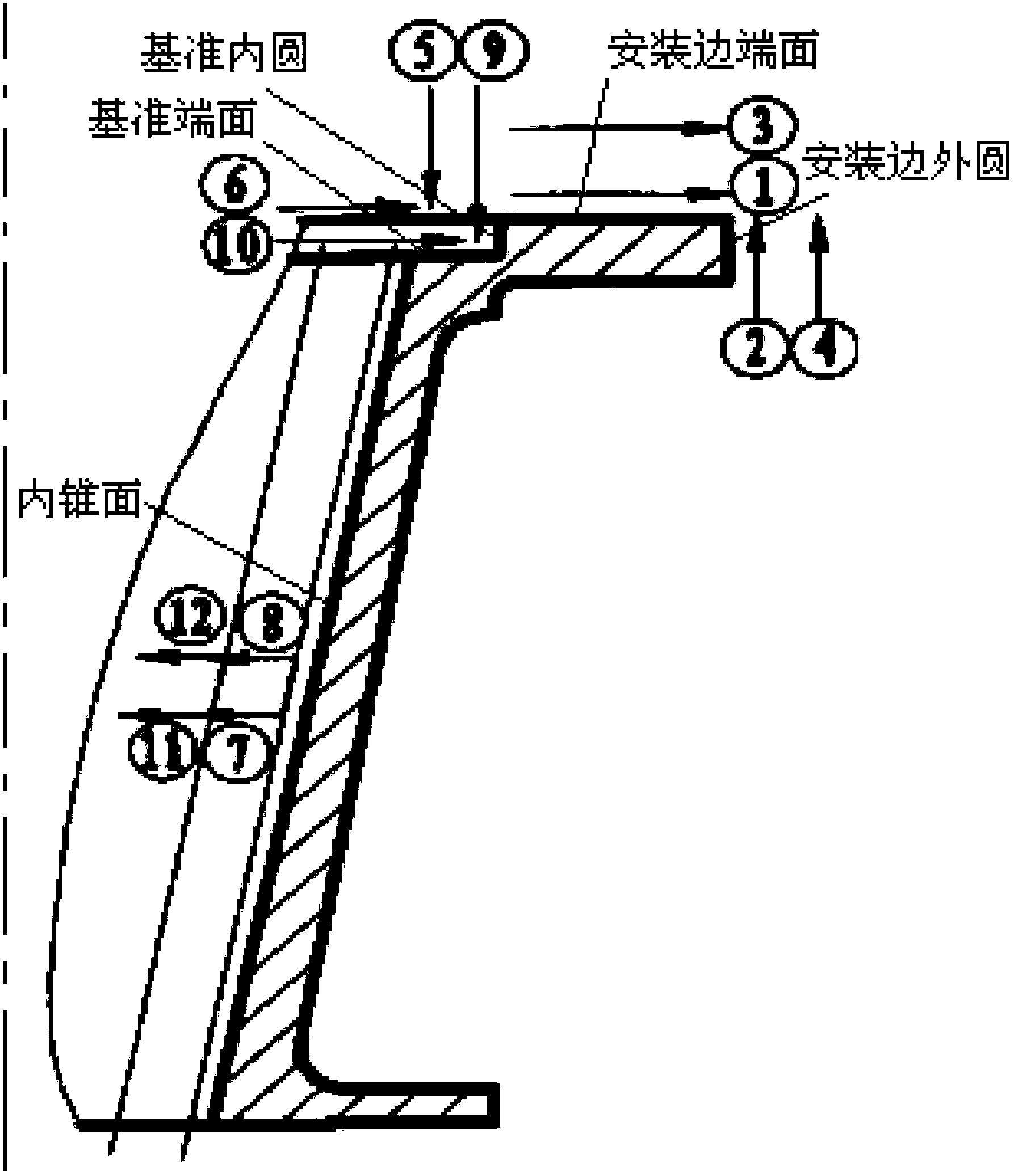
[0048] The cutting tool path planning method for machining metal parts is aimed at metal parts that are easily deformed to be processed (the shape feature requirements are mainly disk parts, shaft parts, casing parts, and ring parts, and the blank requirements are mainly: structural steel, titanium, etc. alloy, high-temperature alloy forging) processing technology formulation; the requirements of the cutting tool path planning method for mechanically processing metal parts are:

[0049] According to the design structure of the part, the precision requirement and the size of the blank machining allowance, arrange the processing times of each surface of the part and the sequential processing sequence of all the processed surfaces, arrange the cutting direction and feeding direction of the tool for each cutting, and use In the form of illustration, the processing times, processing sequence, tool cutting direction and tool feeding direction are marked in the process specification. ...

Embodiment 2

[0064] Embodiment 2 The basic idea of ​​this embodiment is the same as that of Embodiment 1, the difference is that:

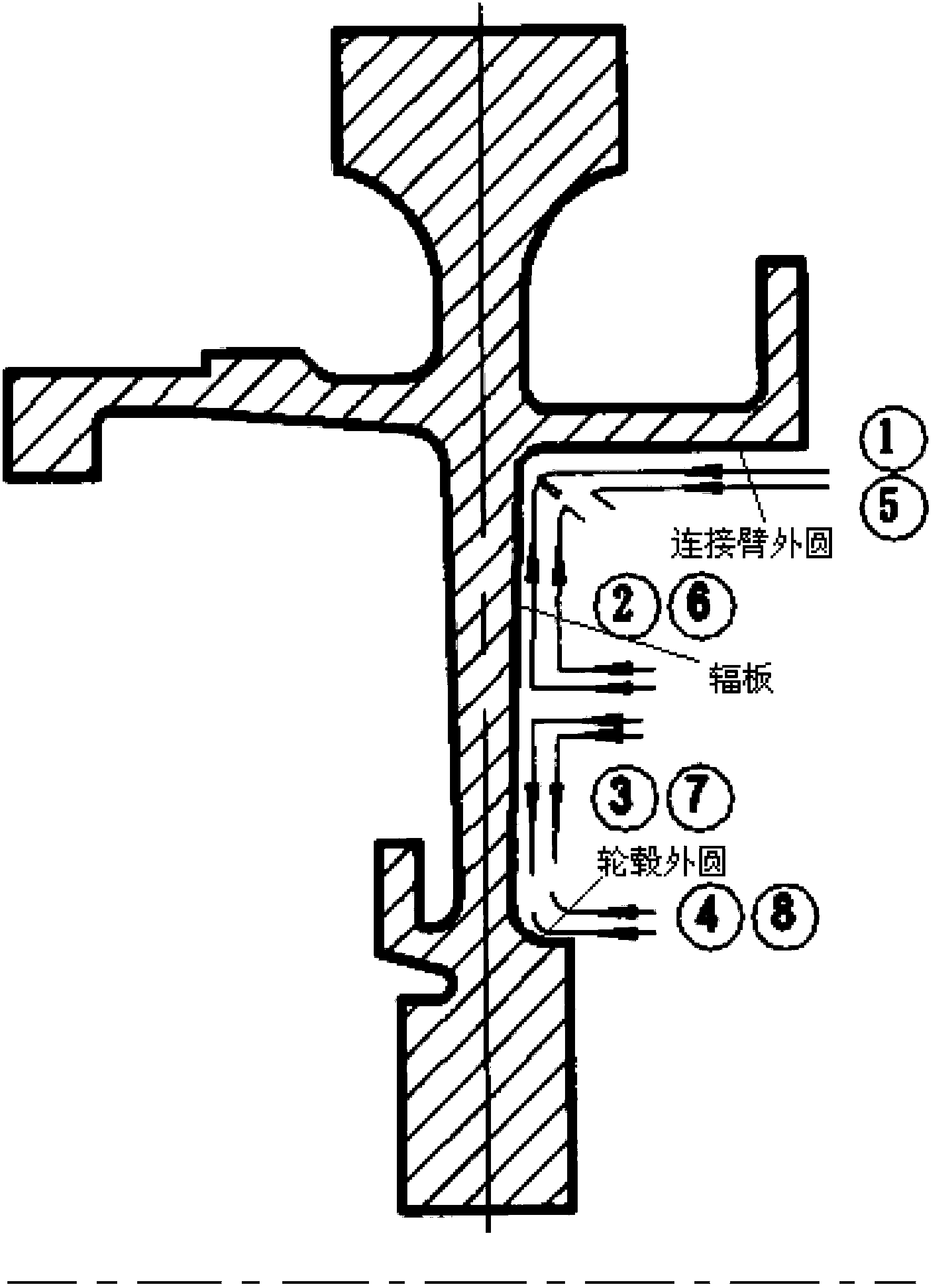
[0065] For the surface roughness of the processed parts is Ra1.6, the precision is ±0.1mm, the machining allowance before processing is 1.0±0.2mm, the material is supplied after aging treatment, the hardness is HB (d) ≥ 338, and the material is a certain high temperature alloy GH4169 For disc turning webs, the blank is die forging, and the cutting tool path planning method meets the following requirements:

[0066] The method of removing the allowance layer by layer is adopted, that is, the allowance is removed in two layers according to the sequence number ①-⑧, the relative cutting method is adopted at the inner fillet transition, and the opposite cutting cutting method is adopted at the radial plate;

[0067] see figure 2 , apply the ① and ⑤ methods described in claim 2; the specific cutting tool path planning methods of each part meet the following requir...

Embodiment 3

[0068] Embodiment 3 The basic idea of ​​this embodiment is the same as that of Embodiment 1, the difference is that:

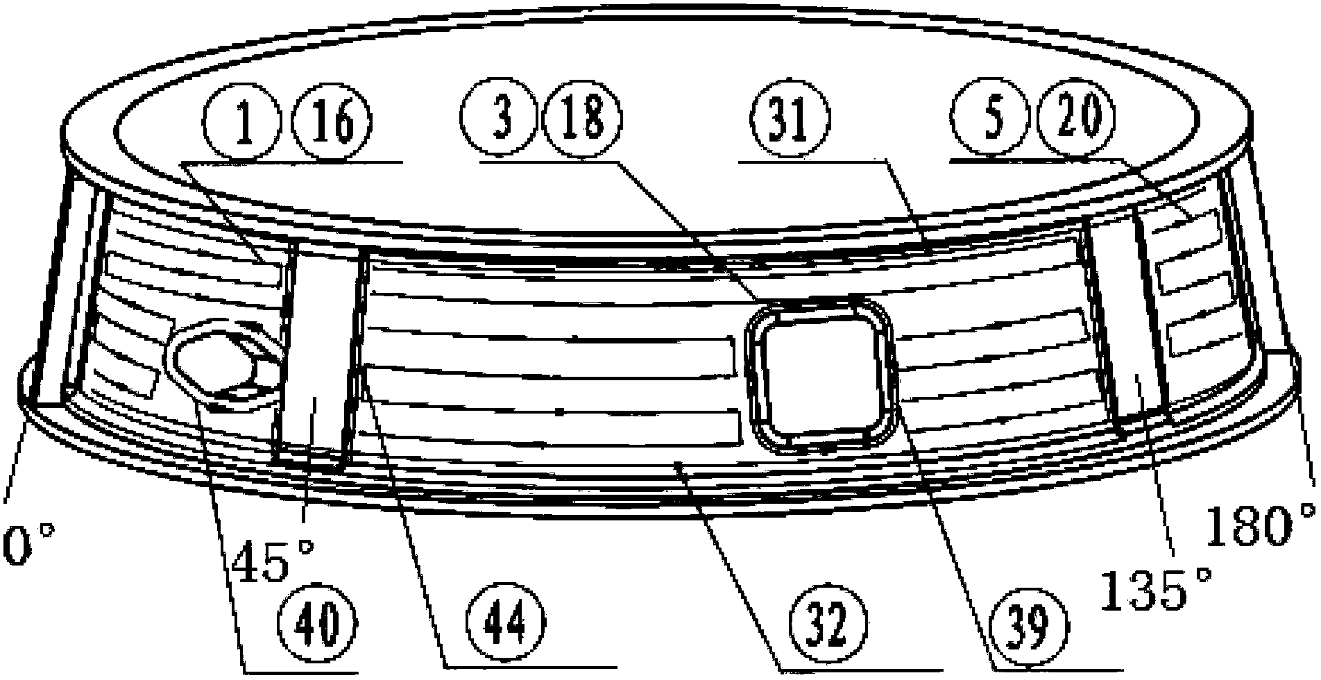
[0069] For the surface milling of a casing with a machining allowance of 3.0±0.5mm and a material made of superalloy GH907, the cutting tool path planning method meets the following requirements: see image 3, the machining allowance is removed in two layers by layered cutting method; the cutting sequence adopts the method of symmetrically removing the allowance of the relative machining surface (only the cutting method in the range of 0°-180° is marked in the figure, and the interval of 180°-360° is not marked In the figure, the serial number is the processing sequence number, that is, first milling the 0°-45° interval according to the processing sequence ①, and then milling the area between 180°-225° of the relative part according to the processing sequence ②, Then process the 45°-135° interval according to the processing sequence ③, and then mill the area b...


PUM


Abstract

The invention provides a cutting and feeding path planning method applied to mechanical machining of metal components, which aims at planning a machining technique of easily-deformed metal components to be machined. The cutting and feeding path planning method applied to the mechanical machining of the metal components is characterized in that the requirements are as follows: according to the design structure, the precision requirement and the size of blank machining allowance of a component, the machining times of each surface and the machining sequence of all machining surfaces of the component are arranged, and a cutting direction and a feeding direction of a cutter in each cutting process are arranged. According to the cutting and feeding path planning method applied to the mechanical machining of the metal components, which are provided by the invention, the peak value of residual stress of the interior of the machined component is remarkably reduced, the state of the component is improved, the precision retainability is good, a thermal treatment process for removing the internal residual stress is simplified or eliminated, the work efficiency is improved, the cost is reduced, and an expectable larger economical value and an expectable social value are provided.

Description

Technical field: [0001] The invention relates to the related technical field of the tool path in machining and cutting methods, and in particular provides a cutting tool path planning method for machining metal parts. Background technique: [0002] In the prior art, the processing technology of parts and components in the aero-engine manufacturing industry has the following general characteristics: the cutting tool path is not marked in the machining process. Usually, the cutting tool path of the ordinary machining process is determined by the operator according to his own processing habits, and the cutting tool path of the NC machining process is determined by the NC programmer according to his own experience and the processing habits of the workers. The deformation is serious, which affects the assembly and performance of the engine. Regarding the influence of the cutting tool path on the surface quality of the product, the relationship between the cutting tool path and t...

Claims


Application Information

Patent Timeline
IPC IPC(8): B23P17/00
CPCB23Q15/00
Inventor 王聪梅齐晓丽王丽花陈国文卢成玉
Owner SHENYANG LIMING AERO-ENGINE GROUP CORPORATION
Why Eureka
Try Eureka