SWSR (SunWay Sulfur recovery)-1 device and technique

A technology of sulfur recovery and process, which is applied in the field of new process of sulfur recovery and tail gas treatment, can solve the problems of high safety control requirements, sulfur recovery effect cannot meet environmental protection requirements, and long process flow, so as to achieve safe and reliable process, energy saving, The effect of short process flow

Active Publication Date: 2014-01-01
SHANDONG SUNWAY PETROCHEMICAL ENGINEERING CO LTD +1
View PDF4 Cites 48 Cited by
  • Summary
  • Abstract
  • Description
  • Claims
  • Application Information

AI Technical Summary

Problems solved by technology

The process is long, requires the use of hydrogenation technology, and has high safety control requirements for the devi

Method used


Image

  • SWSR (SunWay Sulfur recovery)-1 device and technique

Examples


Embodiment 1

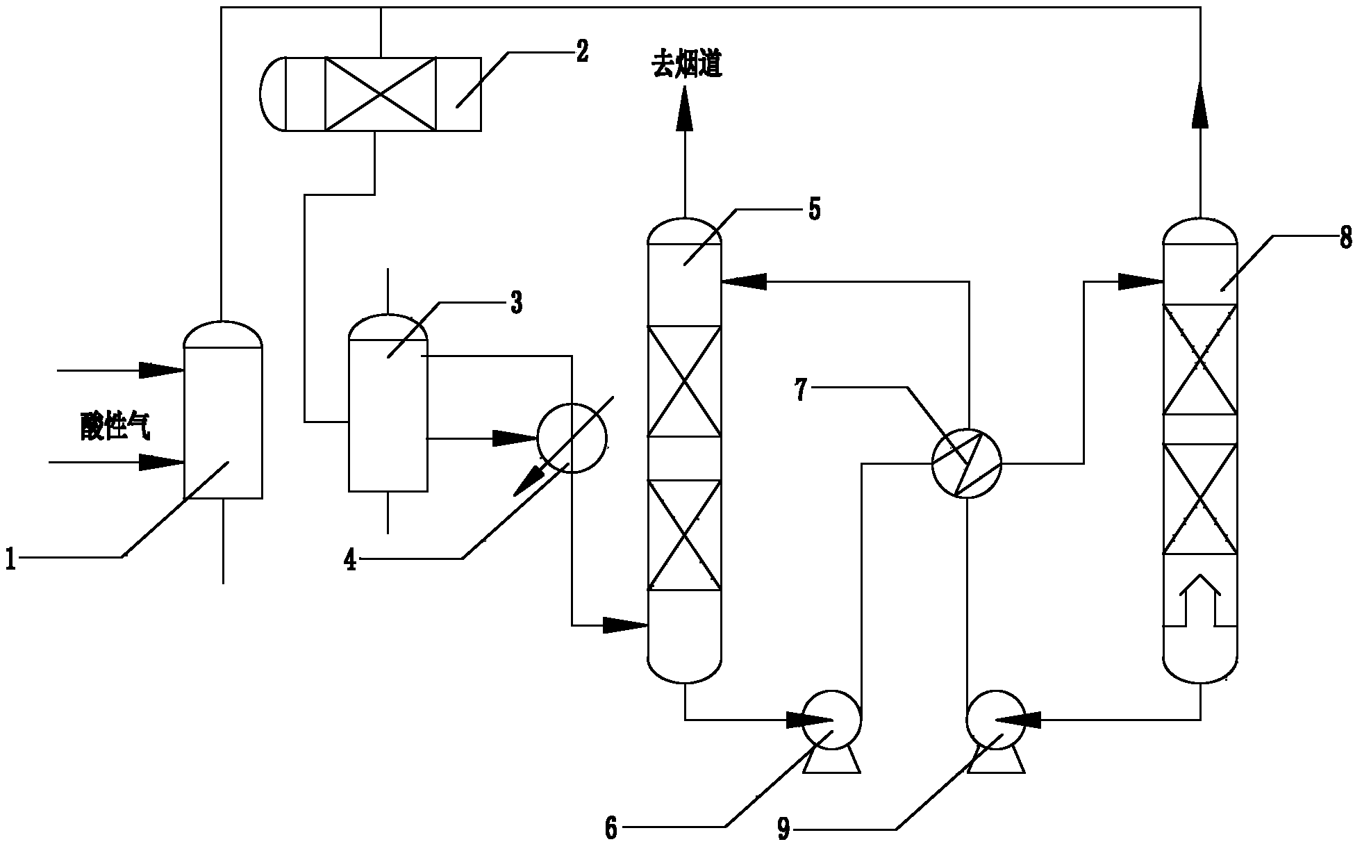
[0042] Such as figure 1 The shown SWSR-1 sulfur recovery unit includes sulfur production combustion furnace 1, Claus reaction system 2, sulfur production tail gas incinerator 3, SO-enriched 2 Process gas heat exchanger 4, SO 2 Absorption tower 5, rich liquid pump 6, lean rich liquid heat exchanger 7, SO 2 Regeneration tower 8 and lean liquid feed pump 9;

[0043] The connection method is as follows: Sulfur production burner 1 is sequentially connected to Claus reaction system 2, sulfur production tail gas incinerator 3, and SO rich 2 Process gas heat exchanger 4 and SO 2 The lower part of the absorption tower 5, SO 2 The bottom of the absorption tower 5 is connected to the rich liquid pump 6, and the rich liquid pump 6 is connected to the lean-rich liquid heat exchanger 7, and the lean-rich liquid heat exchanger 7 is connected to the SO 2 Upper connection of regeneration column 8, SO 2 The bottom of the regeneration tower 8 is connected to the lean liquid feed pump 9, th...

Embodiment 2

[0058] Such as figure 1 The shown SWSR-1 sulfur recovery unit includes sulfur production combustion furnace 1, Claus reaction system 2, sulfur production tail gas incinerator 3, SO-enriched 2 Process gas heat exchanger 4, SO 2 Absorption tower 5, rich liquid pump 6, lean rich liquid heat exchanger 7, SO 2 Regeneration tower 8 and lean liquid feed pump 9;

[0059] The connection method is as follows: Sulfur production burner 1 is sequentially connected to Claus reaction system 2, sulfur production tail gas incinerator 3, and SO rich 2 Process gas heat exchanger 4 and SO 2 The lower part of the absorption tower 5, SO 2 The bottom of the absorption tower 5 is connected to the rich liquid pump 6, and the rich liquid pump 6 is connected to the lean-rich liquid heat exchanger 7, and the lean-rich liquid heat exchanger 7 is connected to the SO 2 Upper connection of regeneration column 8, SO 2 The bottom of the regeneration tower 8 is connected to the lean liquid feed pump 9, th...

Embodiment 3

[0074] Such as figure 1 The shown SWSR-1 sulfur recovery unit includes sulfur production combustion furnace 1, Claus reaction system 2, sulfur production tail gas incinerator 3, SO-enriched 2 Process gas heat exchanger 4, SO 2 Absorption tower 5, rich liquid pump 6, lean rich liquid heat exchanger 7, SO 2 Regeneration tower 8 and lean liquid feed pump 9;

[0075] The connection method is as follows: Sulfur production combustion furnace 1 is sequentially connected to Claus reaction system 2, sulfur production tail gas incinerator 3, and SO rich 2 Process gas heat exchanger 4 and SO 2 The lower part of the absorption tower 5, SO 2 The bottom of the absorption tower 5 is connected to the rich liquid pump 6, and the rich liquid pump 6 is connected to the lean-rich liquid heat exchanger 7, and the lean-rich liquid heat exchanger 7 is connected to the SO 2 Upper connection of regeneration column 8, SO 2 The bottom of the regeneration tower 8 is connected to the lean liquid fee...


PUM


Abstract

The invention relates to an SWSR (SunWay Sulfur recovery)-1 device and technique. The invention relates to a tail gas treatment combination device and technique by adopting Claus sulfur recovery and ionic liquid cycle absorption process. The device comprises a sulfur production burning furnace, a Claus reaction system, a sulfur production tail gas incinerator, a rich SO2 process gas heat exchanger, an SO2 absorption tower, a rich liquid pump, a lean and rich liquid heat exchanger, an SO2 regeneration tower and a lean liquid feed pump. The technique comprises the steps: (1) enabling hydrogen sulfide-containing acid gas to generate a Claus reaction, and recovering sulfur and heat energy in the reaction process; (2) burning sulfur production tail gas to generate SO2; (3) removing SO2 from rich SO2 process gas through an ionic liquid absorption tower; and (4) feeding rich SO2 ionic liquid into a regeneration tower for separating and regenerating sulfur. The ionic liquid is an aqueous solution which takes organic positive ions and inorganic anions as main components and a little amount of activating agent and antioxidant as additives. The SWSR-1 device and technique are low in equipment investment, high in material safety, short in technique flow, safe and reliable in technique processes, high in SO2 recovery rate, and the content of SO2 in effluent gas can be reduced by 50ppm below which can meet the national regulation requirement.

Description

technical field [0001] The invention relates to a new process suitable for sulfur recovery and tail gas treatment, in particular to a new sulfur recovery and tail gas treatment process formed by optimizing and improving a conventional Claus process and an ionic liquid recovery process for sulfur dioxide. Background technique [0002] my country has been advocating energy conservation and emission reduction work, strictly controlling the emission of sulfur dioxide in the atmosphere. Before 2012, the emission concentration of sulfur dioxide stipulated by the national standard was no higher than 960mg / g. At present, the relevant national departments are planning to revise the comprehensive emission standard of air pollutants, requiring the concentration of sulfur dioxide emission from newly built sulfur plants to be less than 400mg / Nm 3 (The emission concentration in specific areas is less than 200mg / Nm 3 ). Sinopec actively implements the green and low-carbon development str...

Claims


Application Information

Patent Timeline
IPC IPC(8): C01B17/04C01B17/54B01D53/14F23G7/06
Inventor 范西四汪志和林彩虹肖九高
Owner SHANDONG SUNWAY PETROCHEMICAL ENGINEERING CO LTD
Why Eureka
Try Eureka