Chemical tail gas deodorization device and deodorization method

A technology for chemical exhaust gas and chemical equipment, which is applied in chemical instruments and methods, separation methods, and dispersed particle separation, etc., can solve the problems of increased processing costs, inconvenient processing, complicated procedures, etc., to reduce sulfur dioxide content and improve purity and quality. , the effect of reducing pollution

Inactive Publication Date: 2015-11-18
CHANGZHOU JINHAILONG MACHINE MFG
View PDF4 Cites 2 Cited by
  • Summary
  • Abstract
  • Description
  • Claims
  • Application Information

AI Technical Summary

Problems solved by technology

[0002] The waste gas produced by the nitrogen fertilizer industry mainly contains nitrogen oxides, urea dust, carbon monoxide, ammonia, sulfur dioxide, methane, etc. Some of the impurities and gases can be recovered by dissol

Method used


Image

  • Chemical tail gas deodorization device and deodorization method

Examples


Example Embodiment

[0024] Example 1:

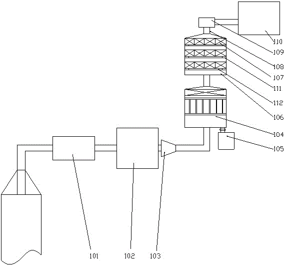
[0025] Such as figure 1 As shown, a chemical exhaust gas deodorization equipment includes a high-pressure dissolved air pump 101 connected to the chemical equipment through a pipeline;

[0026] The high-pressure dissolved air pump 101 is connected to the closed water tank 102 through a pipeline, the output end of the closed water tank 102 is provided with a jet pump 103, and the output end of the jet pump 103 is connected to the gas-liquid separation chamber 104. The gas-liquid separation chamber 104 is provided with a gas-liquid separator;

[0027] A liquid storage tank 105 is provided at the lower end of the gas-liquid separation chamber 104, and a one-way valve connected to the desulfurization bin 106 is provided at the upper end of the gas-liquid separation chamber 104;

[0028] The desulfurization bin 106 is provided with an adsorption layer 107, the adsorption layer 107 is a honeycomb structure, the surface of the adsorption layer 107 is provided with a calc...

Example Embodiment

[0034] Example 2:

[0035] A method for deodorizing chemical exhaust gas, including the following steps:

[0036] S1: The high-pressure dissolved air pump 101 is used to pressurize the chemical exhaust gas into the closed water tank 102, so that the ammonia and air in the chemical exhaust gas are pressurized and transported to the closed water tank 102, a large amount of air squeezes the ammonia dissolved in the water, and the water absorbs Part of sulfur dioxide;

[0037] S2: Start the jet pump 103 to atomize the ammonia dissolved in the water and spray it out at high speed, so that the ammonia enters the gas-liquid separation chamber 104 and is separated from the water through the gas-liquid separator, and the remaining sulfur dioxide and ammonia enter the desulfurization bin through the gas-liquid separator together 106;

[0038] S3: Start the gas pump to generate negative pressure in the desulfurization bin 106, and accelerate the gas to pass through the desulfurization bin 106. ...


PUM


Abstract

The invention discloses a chemical tail gas deodorization device. The device comprises a high-pressure gas dissolution pump connected with chemical equipment through a pipeline, the high-pressure gas dissolution pump is connected with an airtight water tank through a pipeline, a jet pump is arranged at the output end of the airtight water tank, the output end of the jet pump is connected with a gas-liquid separation chamber, and a gas-liquid separator is arranged in the gas-liquid separation chamber; a liquid storage tank is arranged at the lower end of the separation chamber, and a one-way valve connected with a desulfuration chamber is arranged at the upper end of the gas-liquid separation chamber; an adsorption layer is arranged in the desulfuration chamber and adopts a honeycomb structure, a calcification desulfuration agent is arranged on the surface of the adsorption layer, a gas outlet is formed in the end, away from the one-way valve, of the desulfuration chamber, a steam purifier is arranged at the gas outlet, and the output end of the steam purifier is connected with the gas storage tank through a gas sucking pump. The chemical tail gas deodorization device is simplified, and ammonia and sulfur are separated.

Description

technical field [0001] The invention relates to a chemical tail gas deodorization device and a deodorization method, in particular to the tail gas treatment in the nitrogen fertilizer industry. Background technique [0002] The exhaust gas produced by the nitrogen fertilizer industry mainly contains nitrogen oxides, urea dust, carbon monoxide, ammonia, sulfur dioxide, methane, etc. Some of the impurities and gases can be recovered by dissolving in water, but after dissolving in water, the liquid is discharged It will cause water pollution again, which is inconvenient for follow-up treatment, and leads to complicated procedures and increased treatment costs. Contents of the invention [0003] The purpose of the present invention is to provide a chemical tail gas deodorization equipment and deodorization method, which can simplify the equipment and realize the separation of ammonia and sulfur. [0004] The present invention is realized through the following technical soluti...

Claims


Application Information

Patent Timeline
IPC IPC(8): B01D53/78B01D53/04B01D53/26B01D53/58B01D53/50
Inventor 赵燕春
Owner CHANGZHOU JINHAILONG MACHINE MFG
Why Eureka
Try Eureka