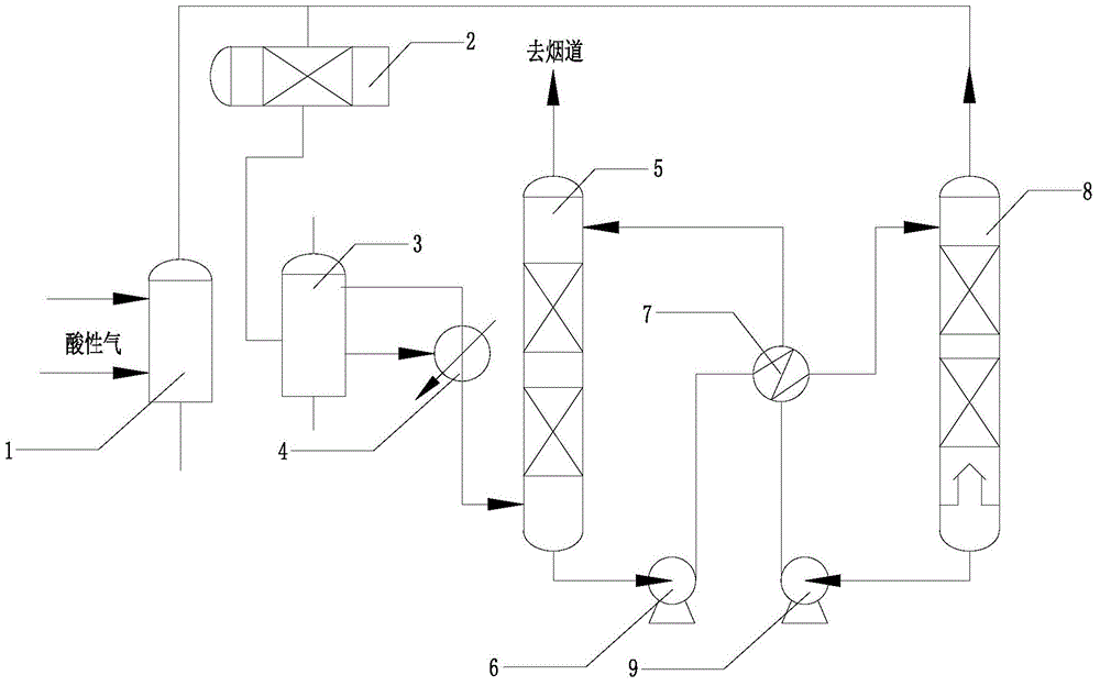
swsr-1 sulfur recovery process
A technology of sulfur recovery and process, which is applied in the field of new process of sulfur recovery and tail gas treatment, can solve the problems of high safety control requirements, sulfur recovery effect cannot meet environmental protection requirements, and long process flow, so as to achieve safe and reliable process, energy saving, The effect of short process flow
- Summary
- Abstract
- Description
- Claims
- Application Information
AI Technical Summary
Problems solved by technology
Method used
Image
Examples
Embodiment 1
[0042] Such as figure 1 The shown SWSR-1 sulfur recovery unit includes sulfur production combustion furnace 1, Claus reaction system 2, sulfur production tail gas incinerator 3, SO-enriched 2 Process gas heat exchanger 4, SO 2 Absorption tower 5, rich liquid pump 6, lean rich liquid heat exchanger 7, SO 2 Regeneration tower 8 and lean liquid feed pump 9;
[0043] The connection method is as follows: Sulfur production burner 1 is sequentially connected to Claus reaction system 2, sulfur production tail gas incinerator 3, and SO rich 2 Process gas heat exchanger 4 and SO 2 The lower part of the absorption tower 5, SO 2 The bottom of the absorption tower 5 is connected to the rich liquid pump 6, and the rich liquid pump 6 is connected to the lean-rich liquid heat exchanger 7, and the lean-rich liquid heat exchanger 7 is connected to the SO 2 Upper connection of regeneration column 8, SO 2 The bottom of the regeneration tower 8 is connected to the lean liquid feed pump 9, th...
Embodiment 2
[0058] Such as figure 1 The shown SWSR-1 sulfur recovery unit includes sulfur production combustion furnace 1, Claus reaction system 2, sulfur production tail gas incinerator 3, SO-enriched 2 Process gas heat exchanger 4, SO 2 Absorption tower 5, rich liquid pump 6, lean rich liquid heat exchanger 7, SO 2 Regeneration tower 8 and lean liquid feed pump 9;
[0059] The connection method is as follows: Sulfur production burner 1 is sequentially connected to Claus reaction system 2, sulfur production tail gas incinerator 3, and SO rich 2 Process gas heat exchanger 4 and SO 2 The lower part of the absorption tower 5, SO 2 The bottom of the absorption tower 5 is connected to the rich liquid pump 6, and the rich liquid pump 6 is connected to the lean-rich liquid heat exchanger 7, and the lean-rich liquid heat exchanger 7 is connected to the SO 2 Upper connection of regeneration column 8, SO 2 The bottom of the regeneration tower 8 is connected to the lean liquid feed pump 9, th...
Embodiment 3
[0074] Such as figure 1 The shown SWSR-1 sulfur recovery unit includes sulfur production combustion furnace 1, Claus reaction system 2, sulfur production tail gas incinerator 3, SO-enriched 2 Process gas heat exchanger 4, SO 2 Absorption tower 5, rich liquid pump 6, lean rich liquid heat exchanger 7, SO 2 Regeneration tower 8 and lean liquid feed pump 9;
[0075] The connection method is as follows: Sulfur production burner 1 is sequentially connected to Claus reaction system 2, sulfur production tail gas incinerator 3, and SO rich 2 Process gas heat exchanger 4 and SO 2 The lower part of the absorption tower 5, SO 2 The bottom of the absorption tower 5 is connected to the rich liquid pump 6, and the rich liquid pump 6 is connected to the lean-rich liquid heat exchanger 7, and the lean-rich liquid heat exchanger 7 is connected to the SO 2 Upper connection of regeneration column 8, SO 2 The bottom of the regeneration tower 8 is connected to the lean liquid feed pump 9, th...
PUM
 Abstract
Description
Claims
Application Information
 - R&D
- Intellectual Property
- Life Sciences
- Materials
- Tech Scout
- Unparalleled Data Quality
- Higher Quality Content
- 60% Fewer Hallucinations
Browse by: Latest US Patents, China's latest patents, Technical Efficacy Thesaurus, Application Domain, Technology Topic, Popular Technical Reports.
© 2025 PatSnap. All rights reserved.Legal|Privacy policy|Modern Slavery Act Transparency Statement|Sitemap|About US| Contact US: help@patsnap.com

