
Ultra-thin heat pipe

A technology of ultra-thin heat pipes and pipe bodies, which is applied in the direction of indirect heat exchangers, lighting and heating equipment, etc., and can solve the problem of poor permeability, limited porosity and heat transfer efficiency, and axial heat transfer of heat pipes with sintered powder cores. The capacity is small and other problems, to achieve the effect of enhancing axial heat transfer capacity, saving materials, and enhancing thermal conductivity

Inactive Publication Date: 2014-01-01
KUN SHAN DOTOP METAL TECH CO LTD
View PDF7 Cites 5 Cited by
  • Summary
  • Abstract
  • Description
  • Claims
  • Application Information

AI Technical Summary

Problems solved by technology

[0005] However, the permeability of sintered powder core heat pipes is poor, so the axial heat transfer capacity is smaller than that of axial channel type heat pipes, and the powder sintered part inside the existing sintered powder core heat pipes, the surface Smooth, resulting in limited porosity and heat transfer efficiency, not maximizing higher thermal conductivity

Method used


Image

  • Ultra-thin heat pipe
  • Ultra-thin heat pipe
  • Ultra-thin heat pipe

Examples


Embodiment 1

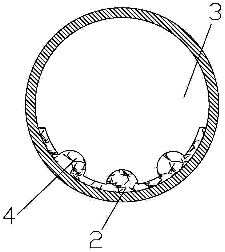
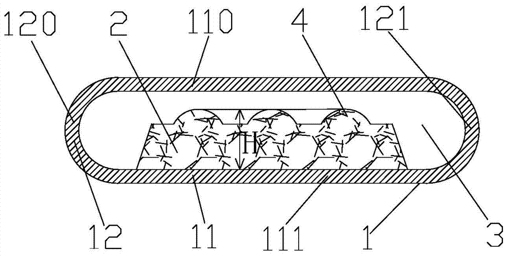
[0038] like figure 1 and figure 2 As shown, an ultra-thin heat pipe provided in this embodiment includes a pipe body 1 , and the pipe body 1 includes a middle side wall 11 and an end side wall 12 connected to the middle side wall 11 . Wherein, the tube body 1 is a copper tube with an inner diameter of 6 mm or 8 mm and a wall thickness of 0.2 mm, or an aluminum tube, a stainless steel tube or a titanium tube of the above specifications. The middle side wall 11 is a straight pipe wall, and the cross section of the end side wall 12 is arc-shaped, preferably semi-circular.

[0039] In this embodiment, the middle sidewall 11 includes a first middle sidewall 110 and a second middle sidewall 111 , and the end sidewall 12 includes a first end sidewall 120 and a second end sidewall 121 . A first end of the first middle sidewall 110 is connected to a first end of the first end sidewall 120 , and a second end of the first middle sidewall 110 is connected to a first end of the second e...

Embodiment 2

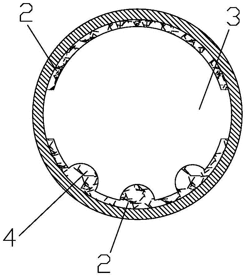
[0044] like image 3 and Figure 4 As shown, the difference between this embodiment and Embodiment 1 is that in this embodiment, the inner wall of the first middle side wall 110 and the inner wall of the second middle side wall 111 are provided with a metal powder sintered part 2, and both A steam channel 3 is formed between the first metal powder sintered part 2 and the middle side wall 11 and the end side wall 12, wherein a protrusion 4 is provided on the side of the metal powder sintered part 2 away from the second middle side wall 111, although the steam The space of the channel is smaller than the space of the steam channel in Embodiment 1, but the flow rate of the steam and the heat transfer efficiency of the heat pipe are improved, and the thermal conductivity is good, so it is more suitable as a heat sink for micro-equipment.


PUM

PropertyMeasurementUnit
widthaaaaaaaaaa
widthaaaaaaaaaa

Abstract

The invention relates to the field of heat pipe structures, in particular to an ultra-thin heat pipe. The ultra-thin heat pipe comprises a pipe body, wherein the pipe body comprises a middle side wall and end portion side walls connected with the middle side wall, the inner wall of the middle side wall is provided with a metal powder sintering portion, the side, away from the middle side wall, of the metal powder sintering portion is provided with a plurality of evenly distributed protrusions, and steam channels are formed among the metal powder sintering portion, the protrusions, the middle side wall and the end portion side walls. The metal powder sintering portion is provided with the protrusions which are intermittently or continuously arranged, a groove is formed between every two adjacent protrusions, the groove-shaped fluid return channels are formed in the spaces formed by the grooves and the middle side wall, axial heat transferring ability of the heat pipe is effectively reinforced, additionally, due to arrangement of the protrusions, the porosity is increased, fluid return resistance in the heat pipe is reduced, heat transferring efficiency is improved, heat conductive performance of the heat pipe is reinforced, and meanwhile, materials and production cost are saved.

Description

technical field [0001] The invention relates to the field of heat pipe structure, in particular to an ultra-thin heat pipe. Background technique [0002] As the product structure of the microcomputer industry (notebook computer, tablet computer) is moving towards lighter, thinner and smaller, the processor is developing in the direction of high speed and high power. However, in the process of continuous improvement of product performance, the problems caused by its heat generation are becoming more and more serious, and the heat generation of electronic components is increasing day by day. In order to solve the aforementioned problems, many passive heat transfer elements have been proposed one after another, such as: ultra-thin heat pipes, loop heat pipes , flat heat pipe, steam bath soaker and fins, etc. [0003] The heat pipe is a heat dissipation device with high thermal conductivity. It is composed of a tube shell, a liquid-absorbing core and an end cover. In the evapor...

Claims


Application Information

Patent Timeline
Patent Type & Authority Applications(China)
IPC IPC(8): F28D15/04
CPCF28D15/046F28D15/0233
Inventor 朱胜利
Owner KUN SHAN DOTOP METAL TECH CO LTD
Learn More