
Adjustment and design method for lighting system matching multiple objective lens in extreme ultraviolet lithography machine

An extreme ultraviolet lithography and lighting system technology, applied in the field of lithography lighting design, can solve the problems of increasing manufacturing costs, consuming a lot of manpower and material resources, etc., and achieve the effects of reducing design and manufacturing costs, reducing design costs, and shortening the research and development cycle.

Active Publication Date: 2014-01-01
BEIJING INSTITUTE OF TECHNOLOGYGY
View PDF3 Cites 9 Cited by
  • Summary
  • Abstract
  • Description
  • Claims
  • Application Information

AI Technical Summary

Problems solved by technology

However, in order to further reduce the feature size, the numerical aperture of the projection objective lens will continue to increase, and its corresponding entrance pupil parameters will also change, which leads to the need to redesign the matching illumination system
Obviously, the use of new components will greatly increase the manufacturing cost, and redesigning a new lighting system will also consume a lot of manpower and material resources

Method used


Image

  • Adjustment and design method for lighting system matching multiple objective lens in extreme ultraviolet lithography machine
  • Adjustment and design method for lighting system matching multiple objective lens in extreme ultraviolet lithography machine
  • Adjustment and design method for lighting system matching multiple objective lens in extreme ultraviolet lithography machine

Examples


Embodiment

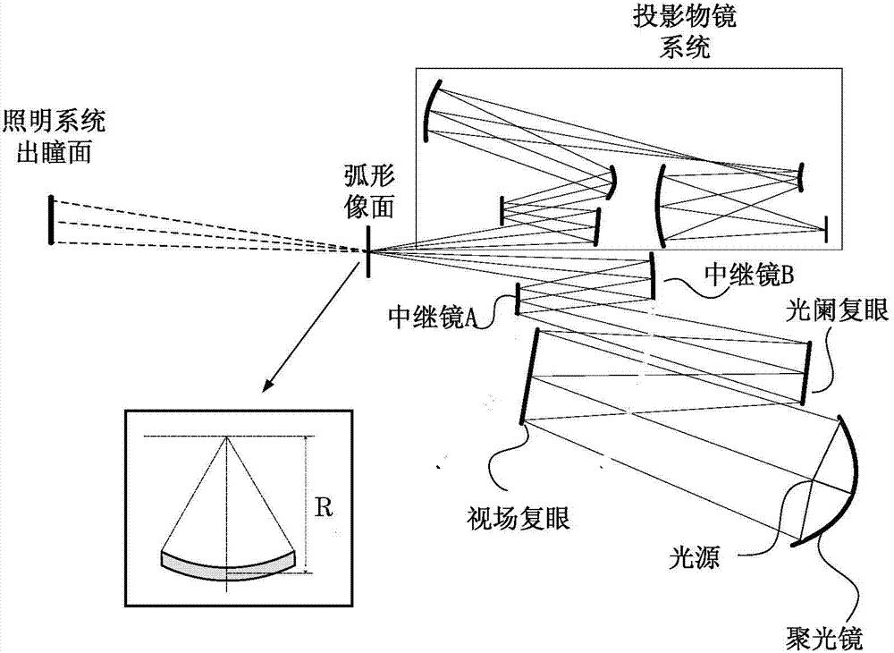
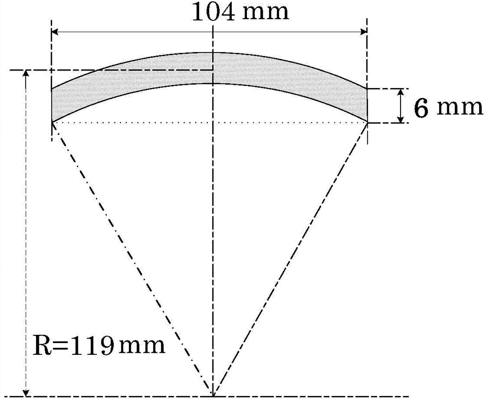
[0045] Table 1 shows three sets of design indexes of lighting systems matched with different projection objectives, wherein the first set is used as the design indexes of the initial lighting system, and the other two sets are obtained according to the design of the present invention. The three systems all use laser plasma light source, and the parameters of the light source condenser are calculated based on the data provided by EUV light source manufacturer Cymer. Its structure is as follows: Figure 4 shown. The size of the curved object plane in all objective lens systems is the same, and its structure is as follows image 3 As shown, but the incident angle of the chief ray and the numerical aperture of the object side are different in each set of the curved object surface, so the entrance pupil parameters are also different. Since the incident angle of the chief ray on the curved object surface in the extreme ultraviolet lithography objective lens system usually varies be...


PUM


Abstract

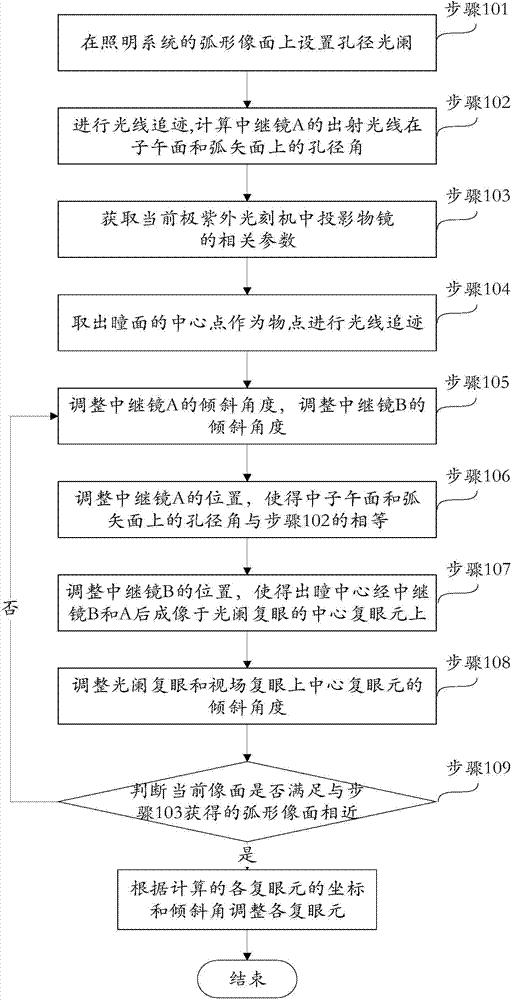
The invention provides an adjustment and design method for a lighting system matching multiple objective lens in an extreme ultraviolet lithography machine. The lighting system applicable to the method includes a light source, a condenser lens, a view field compound eye, a diaphragm compound eye and a relay lens group. The method specifically comprises the steps of: before replacing a projection objective lens of the extreme ultraviolet lithography machine: using ray tracing to calculate the aperture angles of the emergent rays of a relay lens A on a meridian plane and a sagittal plane; after replacing a projection objective lens of the extreme ultraviolet lithography machine: taking out the central point of pupil plane to serve as an object point to perform ray tracing; adjusting the tilt angles and positions of the relay lens A and relay lens B, and adjusting the tilt angles of central compound eye elements on the diaphragm compound eye and the view field compound eye till that the image plane of the current lighting system is close to an arc image plane corresponding to the projection objective lens. By adjusting the lighting system based on the adjustment method provided by the invention, the lighting system matching the projection objective lens system can be obtained, thus greatly reducing the design cost of a projection lithography machine.

Description

technical field [0001] The invention relates to an illumination system adjustment and design method for matching multiple objective lenses in an extreme ultraviolet lithography machine, and belongs to the technical field of lithography illumination design. Background technique [0002] Extreme ultraviolet lithography (EUVL) is a lithography technology that uses EUV rays with a wavelength of 11-14nm as the exposure light source, and is suitable for mass production of integrated circuits with a feature size of 22nm and smaller. The core component of the projection lithography machine is the projection exposure optical system, and the most important components of the system are the illumination system and the projection objective lens system. The main function of the illumination system is to provide uniform illumination for the mask surface, control the exposure dose and realize the off-axis illumination mode. As an important part of the lithography machine, the lighting syst...

Claims


Application Information

Patent Timeline
IPC IPC(8): G03F7/20
CPCG03F7/70141G03F7/705
Inventor 李艳秋梅秋丽刘菲
Owner BEIJING INSTITUTE OF TECHNOLOGYGY
Learn More