One-sided packaged U-shaped hollow fiber membrane element and component

A fiber membrane and hollow technology, applied in the field of membrane separation equipment, can solve the problems of membrane elements such as weak universal design function, inability to combine immersion, internal pressure function, and complicated sealing design, so as to reduce the risk of leakage and improve the membrane quality. The effect of surface utilization and compact structure

Active Publication Date: 2014-01-15
广东中科华膜净水科技有限公司
View PDF7 Cites 16 Cited by
  • Summary
  • Abstract
  • Description
  • Claims
  • Application Information

AI Technical Summary

Problems solved by technology

Invention patent application CN102160966A discloses an external pressure hollow fiber membrane module and its preparation method. The hollow fiber membrane element package of this module is equipped with a central tube and a central tube joint. The ends are respectively sealed at the upper and lower ends of the membrane shell. In order to keep the hollow fiber membranes evenly distributed in the vertical direction without twisting, an equiangular distribution plate is set. The end is also guaranteed to be sealed so that the membrane module will not leak
Invention patent CN101757853B discloses an external pressure hollow fiber membrane module and cleaning system with an anti-pollution structure. The module has a U-shaped membrane filament, and only one end of the membrane element forms a sealing layer. In the sealing layer on one side of the membrane element, since the head and the tail of the U-shaped membrane are not packaged separately, it only has the function of an external pressure component; There are aeration tubes, so this module only has the function of aeration and external pressure. MBR components of membrane bioreactors cannot have both immersion and internal pressure functions. The universal design function of membrane elements is not strong

Method used


Image

  • One-sided packaged U-shaped hollow fiber membrane element and component
  • One-sided packaged U-shaped hollow fiber membrane element and component
  • One-sided packaged U-shaped hollow fiber membrane element and component

Examples


Embodiment 1

[0037] Example 1 One-sided encapsulation of U-shaped hollow fiber membrane elements

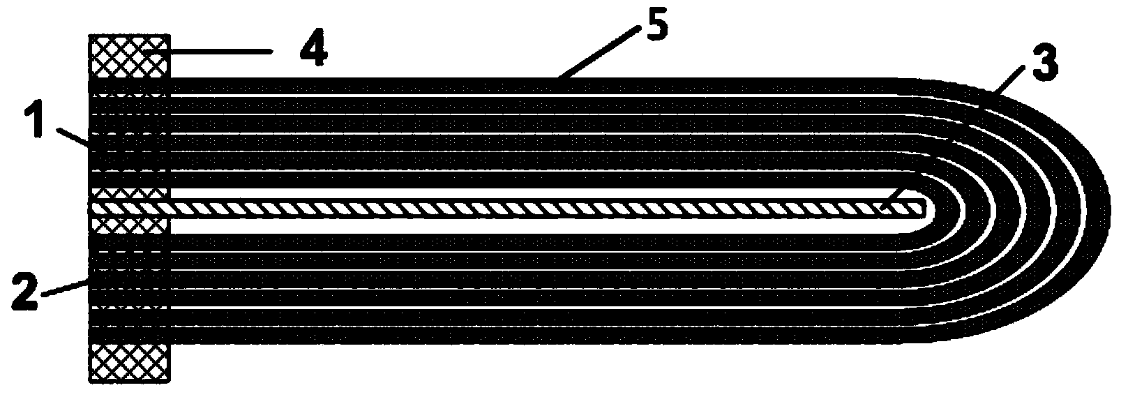
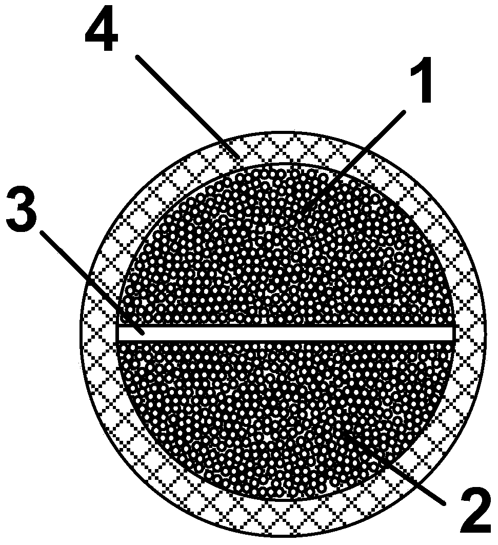
[0038] Such as figure 1 and figure 2As shown, a U-shaped hollow fiber membrane element encapsulated on one side includes a hollow fiber membrane bundle 5, a central diaphragm and a sealing head 4, and the hollow fiber membrane bundle 5 is bent 180 degrees along the central diaphragm to form a U Type hollow fiber membrane bundles, the hollow fiber membrane bundles 5 before and after bending are separated by a central diaphragm, and the two ends of each membrane filament are located on both sides of the central diaphragm. The head end 1, the tail end 2 of the hollow fiber membrane bundle 5 and one end or the proximal end of the central diaphragm are casted and solidified to form the sealing head 4, and the sealing head 4 is opened to form a hollow fiber membrane element. The sealing material used for the sealing head may be epoxy resin, phenolic resin, acrylic sealant, polyurethane sealant, ...

Embodiment 2

[0041] Example 2 Submerged External Pressure Hollow Fiber Membrane Module

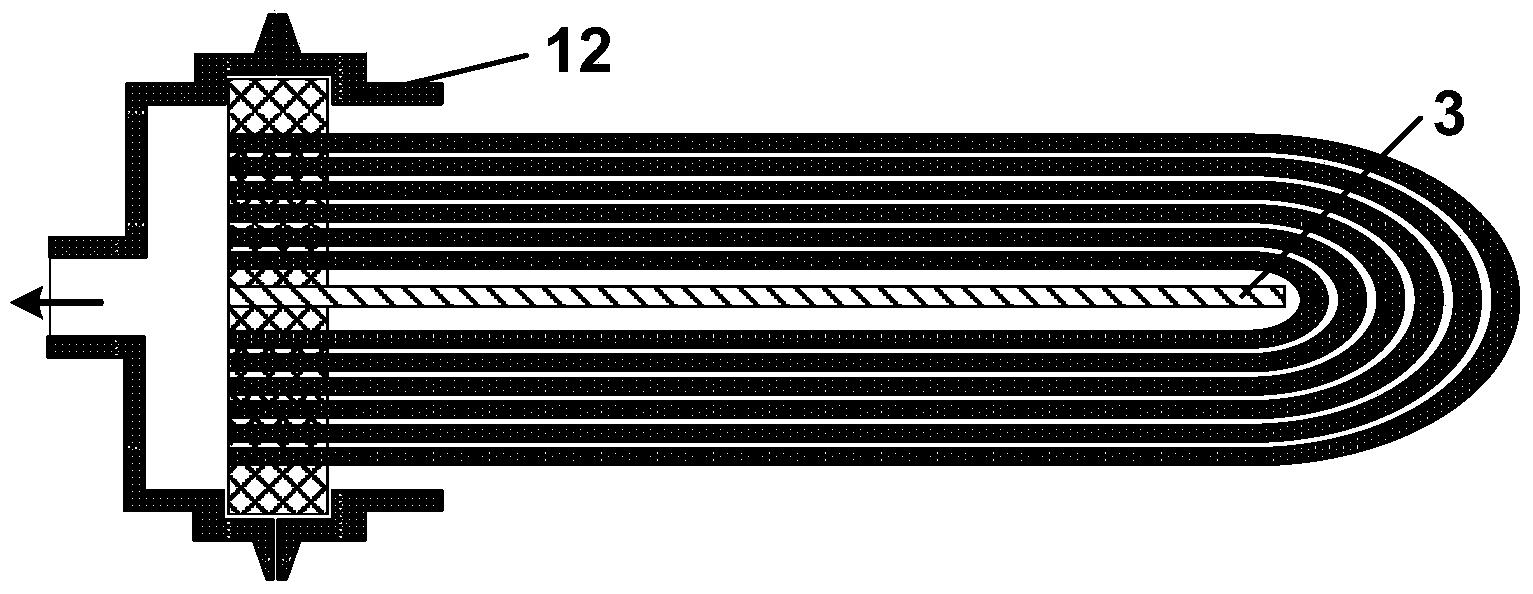
[0042] Such as image 3 As shown, a submerged external pressure hollow fiber membrane module, the hollow fiber membrane module includes an upper end cover 8, a lower end cover 12 and the hollow fiber membrane element, and one end of the upper end cover 8 and the lower end cover 12 Both are provided with openings, and the other ends of the upper end cover 8 and the lower end cover 12 are both sealed and connected with the sealing head 4 , and the lower end cover 12 is tightly connected with the upper end cover 8 . The central transverse partition is a solid partition 3, and the solid partition 3 is sealed in the sealing head 4, and the sealing head 4 is cut flat to expose the hole in the membrane. The hollow fiber membrane element is directly immersed in the feed liquid, the permeate permeates through the membrane surface and collects in the upper end cover 8 and absorbs the produced water, and the pro...

Embodiment 3

[0043] The hollow fiber membrane module of the present invention has a length of 0.5m, a diameter of 4 inches, an effective length of the membrane of 0.8m, and a PVDF outer pressure membrane with an outer diameter of 1mm and an inner diameter of 0.6mm, and a membrane area of ​​2m 2 , The filling rate is 90%. Example 3 Aeration Submerged External Pressure Hollow Fiber Membrane Module

[0044] Such as Figure 4 As shown, the structure of the aeration submerged external pressure hollow fiber membrane module in this embodiment is basically the same as that in Embodiment 2, the only difference is that the central diaphragm is an aeration plate 13, and the aeration plate 13 passes through The transparent sealing layer extends to the outside of the open end of the upper end cover 8, and the shown aeration plate 13 is a hollow porous plate. The membrane filaments and the aeration tube are directly immersed in the feed liquid, the aeration plate 13 is fed with air or ozone, and the a...


PUM

PropertyMeasurementUnit
diameteraaaaaaaaaa
areaaaaaaaaaaa
diameteraaaaaaaaaa

Abstract

The invention discloses a one-sided packaged U-shaped hollow fiber membrane element and component. The hollow fiber membrane element comprises a U-shaped hollow fiber membrane cluster, a sealing head and a central transverse diaphragm, wherein the central transverse diaphragm is positioned inside the U-shaped hollow fiber membrane cluster; the head end and the tail end of the U-shaped hollow fiber membrane cluster, one end of the central transverse diaphragm or a near end part at one end are sealed in the sealing head. According to the hollow fiber membrane element, different upper and lower end covers, membrane shells, inlets/outlets and central transverse diaphragms are matched, different types of hollow fiber membrane elements in external pressure, internal pressure, immersion and aeration can be formed, and the membrane element is high in universality. The hollow fiber membrane element and component adopt a one-sided packaged mode, and the assembling and packaging difficulty is reduced, so that the element is compact in structure, high in flexibility and simple and reasonable in sealing design, and a leakage risk of the element in the using process is reduced.

Description

technical field [0001] The invention relates to the field of membrane separation equipment, in particular to a hollow fiber membrane element and module. Background technique [0002] Membrane separation technology is widely used in the separation, purification, concentration and purification process of substances due to its high efficiency and low energy consumption. The existing membrane elements or membrane modules mainly include several types such as flat plate type, coil type, tubular type and hollow fiber, among which the hollow fiber membrane has the advantages of large membrane area, high module packing density and low cost. It has become a commonly used membrane module type. [0003] The structural design of the membrane module and the sealing performance of the membrane elements have an important impact on the reliability of the operation of the entire membrane separation system. Hollow fiber membranes have high membrane flux and certain flexibility, so making ful...

Claims


Application Information

Patent Timeline
Patent Type & Authority Applications(China)
IPC IPC(8): B01D63/02C02F1/44
Inventor 何勇郭芳威陈顺权杜如虚
Owner 广东中科华膜净水科技有限公司
Why Eureka
Try Eureka