
A phase change heat storage type high wind temperature hot blast stove

A phase change heat storage and hot blast stove technology, applied in blast furnaces, blast furnace details, blast furnace parts, etc., can solve problems such as unfavorable blast furnace production and large temperature difference, and achieve the effects of miniaturizing equipment, improving service life and improving efficiency

Active Publication Date: 2015-09-02
ANGANG STEEL CO LTD
View PDF8 Cites 0 Cited by
  • Summary
  • Abstract
  • Description
  • Claims
  • Application Information

AI Technical Summary

Problems solved by technology

However, due to the temperature change of the checker bricks during the heat exchange process, the temperature difference between the initial air supply and the final air supply is relatively large, which is not conducive to the production of the blast furnace

Method used


Image

  • A phase change heat storage type high wind temperature hot blast stove

Examples


Embodiment 1

[0021] Hot air volume 300000Nm 3 / h conventional hot air stove, the average hot air temperature is 1220°C (the temperature range is reduced from 1250°C (at the beginning of air supply) to 1050°C), and its sensible heat is 525753261.2kJ / cycle. Design without changing the air supply cycle.

[0022] When the high-temperature heat transfer efficiency of the hot blast stove is 20%, 30%, and 50%, the heat transfer heat required by the heat storage ball is 103270753 kJ / cycle, 154906129 kJ / cycle, and 258176882 kJ / cycle from low to high. All are provided by the phase change heat of the energy storage material, and MgF 2 198,597.60 kg of high-temperature energy storage materials, 221,294.47 kg of LiOH medium-temperature energy storage materials, 258,176.88 kg of KOH low-temperature energy storage materials, and a single heat storage ball with a diameter of 400 mm requires 10,920 small balls (including 3,212 high-temperature, 3,854 medium-temperature, and 3,854 low-temperature balls. T...

Embodiment 2

[0025] Same hot air volume 150000Nm 3 / h small hot stove. The average hot air temperature of a conventional hot blast stove is 1200°C (the temperature range is reduced from 1230°C (at the beginning of air supply) to 1020°C), and its sensible heat is 262876630.6kJ / cycle.

[0026] The high-temperature heat transfer efficiency of the hot blast stove remains unchanged, which is still 20%, 30%, and 50%. The heat transfer required by the heat storage ball is 52575326.12 kJ / cycle, 78862989.18 kJ / cycle, and 131438315.3 kJ / cycle from low to high. All are provided by the phase change heat of the energy storage material. LiOH+LIF composite material is selected as the high-temperature energy storage material, and the high-temperature composite energy storage material is 111388.40kg, Na 2 SO 4 / SiO 4 Medium temperature energy storage material 98578.74kg, NaNO 3 The low-temperature energy storage material is 219063.86 kg. The heat storage material is in the shape of a hexagonal column w...


PUM


Abstract

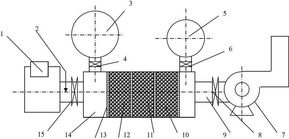
The invention discloses a phase change thermal storage type high blast temperature hot blast stove, which includes a hot blast main pipe, a cold blast main pipe, a thermoregulator and a smoke discharge main pipe connected to a hot blast stove body. And the hot blast main pipe, the cold blast main pipe, the thermoregulator and the smoke discharge main pipe are respectively provided with a hot blast valve, a cold blast valve, a hot smoke valve and a smoke discharge valve. The front of the hot smoke valve is connected to a burner, and the back of the smoke discharge valve is connected to an induced draft fan. The inner cavity of the stove body is divided into a high temperature energy storage material cavity, an intermediate temperate energy storage material cavity, and a low temperature energy storage material cavity in order along a smoke flow direction by perforated shunting partition boards. The energy storage material cavities are filled with a high temperature energy storage material, an intermediate temperature energy storage material, and a low temperature energy storage material in order. The hot blast stove provided by the invention can realize stable high blast temperature. The volume of the hot blast stove can be decreased by changing lattice bricks, consumption of the hot blast stove can be reduced, and at the same time, a blast furnace can be provided with stable high temperature hot blast.

Description

technical field [0001] The invention belongs to the field of recovery and utilization of ironmaking residual energy in metallurgical process, and in particular relates to a phase change heat storage type high blast temperature hot blast stove. Background technique [0002] As an important part of the ironmaking process, the hot blast stove provides heat for the smelting of the blast furnace, and achieving a stable high blast temperature is the goal of the hot blast stove operation. Because the traditional checker bricks are refractory materials used in the existing blast furnace hot blast stove, the temperature resistance is limited, and the blast temperature cannot reach a high level. At the same time, its thermal conductivity and heat storage are limited by the physical properties of the refractory material, requiring a long heat storage time. In this process, it is difficult to achieve a stable high wind temperature due to the change of the material with the flue gas and ...

Claims


Application Information

Patent Timeline
Patent Type & Authority Patents(China)
IPC IPC(8): C21B9/00
Inventor 刘常鹏马光宇张宇贾振李卫东张天赋袁玲王东山
Owner ANGANG STEEL CO LTD
Learn More