Pile type continuous rigid frame bridge and construction method thereof

A pile and rigid frame technology, applied in the field of continuous rigid frame bridges and their construction, can solve the problems of not setting piers, limiting the height of piers, increasing the flexibility of piers, etc. Effect

Active Publication Date: 2014-01-15
SICHUAN DEPT OF TRANSPORTATION HIGHWAY PLANNING PROSPECTING & DESIGN RES INST
View PDF6 Cites 5 Cited by
  • Summary
  • Abstract
  • Description
  • Claims
  • Application Information

AI Technical Summary

Problems solved by technology

However, when the bridge is built after water storage in the mountainous reservoir area, due to the large water depth, high water level, and small height difference between water and land, the height of the bridge pier is limited under a reasonable main girder elevation, and there is even no space for setting up the pier. figure 2 As shown, due to the high water level and the limitation of the main girder and the cap, it is difficult for the continuous rigid frame bridge to use the height of the pier to increase the flexibility of the pier. Temporary structures such as steel cofferdams, steel hanging boxes, etc. require large deep-water construction equipment that is difficult to enter the construction site

Method used


Image

  • Pile type continuous rigid frame bridge and construction method thereof
  • Pile type continuous rigid frame bridge and construction method thereof
  • Pile type continuous rigid frame bridge and construction method thereof

Examples


Embodiment 1

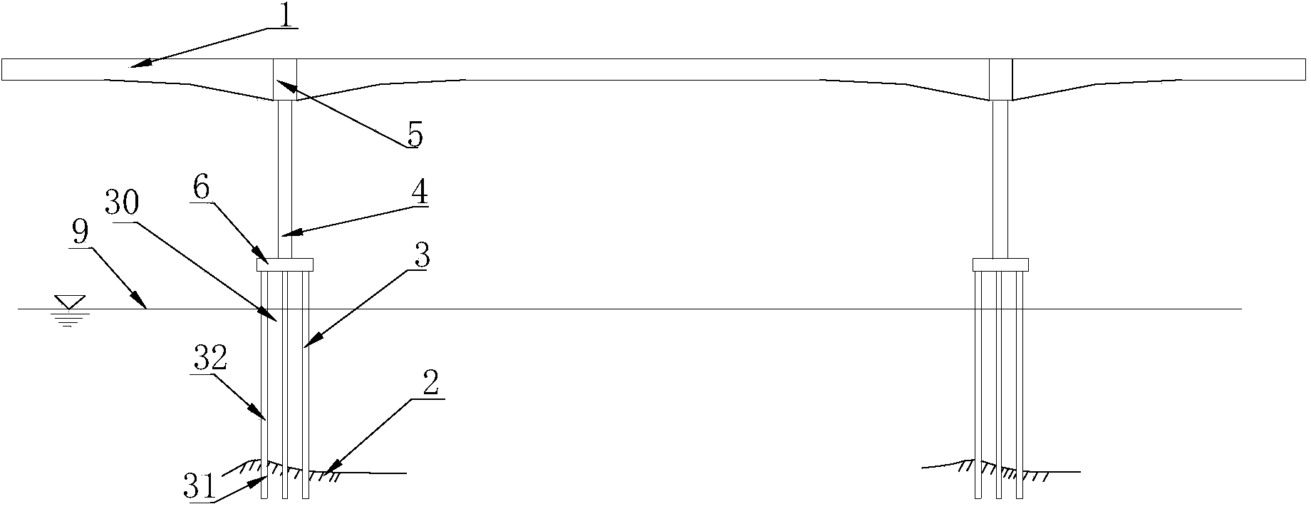
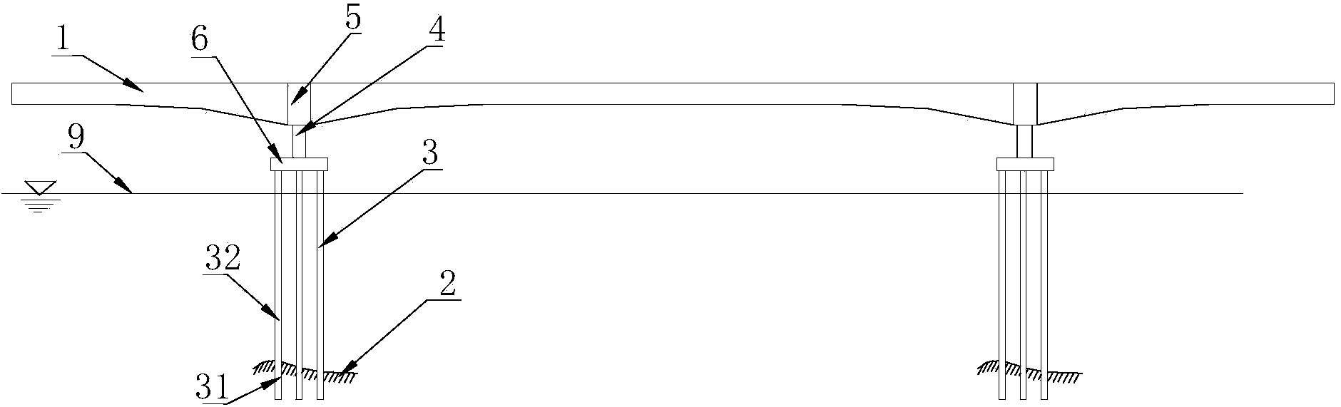
[0117] Such as image 3 As shown, a main beam connection part 5 is arranged between two adjacent span main beams 5, and a pile group foundation 30 is installed and poured under the main beam connection part 5, and the pile group foundation 30 is composed of a group of cast-in-place piles 3 . The top end of each cast-in-place pile 3 is provided with a bottom plate 8 integrated with the girder connecting portion 5 of the bridge deck girder 1 . In order to ensure that the top of the cast-in-situ pile 3 is consolidated with the main beam connection part 5, the horizontal reinforcement at the bottom of the bottom plate 8 is reinforced according to the reinforcement requirements of the cap 6 of the high-pier continuous rigid frame bridge, and the thickness of the main beam connection part 5 and the bottom plate 8 The sum is not less than the thickness of the cap 6 of the continuous rigid frame bridge with high piers.

[0118] The cast-in-place pile 3 is divided into three sections...

Embodiment 2

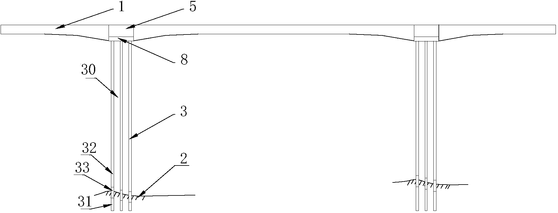
[0131] Such as Figure 4 As shown, the difference between the present embodiment and the first embodiment is that when the width of the deck girder 1 is smaller than the width of the pile group foundation 30, such as Figure 5 As shown, if according to the method of Embodiment 1, part of the cast-in-situ piles 3 cannot be directly connected with the main beam connection portion 5, for this reason, a cap 6 is arranged on the top of the pile group foundation 30, and the cap 6 and the pile group foundation are formed. All cast-in-situ piles 3 of 30 are connected to form an integral support structure, and an upper cap 7 is arranged on the above-mentioned cap 6, and the upper cap 7 is connected with the main beam connection part 5, and the width of the upper cap 7 is the same as that of the main beam 1 The widths are compatible, so that the connection between the main girder 1 of the bridge deck and the cast-in-place pile 3 can be solved.

[0132] In this embodiment, the height of...


PUM


Abstract

The invention discloses a continuous rigid frame bridge suitable for a high-waterline impoundment reservoir area. The pile type continuous rigid frame bridge can meet the requirements for strength and flexibility without a common pier. The pile type continuous rigid frame bridge comprises a girder, two girder connecting parts and a pile group foundation, wherein the two girder connecting parts stride the girder, the pile group foundation is composed of a set of filling piles, and the filling piles are in rigid connection with the girder connecting parts. The filling piles comprise upper columns and lower columns, wherein the upper columns are connected with the girder connecting parts, and the lower columns are poured into a bed rock. Longitudinal steel bars are arranged on the upper columns after the following carrying capacity limiting condition calculation and the normal using limiting condition calculation are carried out. Longitudinal steel bars are arranged on the lower columns according to the file foundation requirement. Pile transition sections are arranged between the lower columns and the upper columns, and the longitudinal steel bars in the pile transition sections are the same as longitudinal reinforcing bars of the upper columns. The invention further provides a construction method for the pile type continuous rigid frame bridge. The pile type continuous rigid frame bridge has the advantages that the anti-seismic requirement is met, construction is convenient, construction cost is saved, and the construction period is shortened.

Description

technical field [0001] The invention relates to a continuous rigid-frame bridge, in particular to a continuous rigid-frame bridge suitable for reservoir areas with high water levels and a construction method thereof. Background technique [0002] The continuous rigid frame bridge is evolved from the T-shaped rigid frame bridge. Its structural characteristics are the continuous beam body and the consolidation of the girder pier. It not only maintains the advantages of the continuous beam without expansion joints and smooth driving, but also maintains the T-shaped rigid frame bridge It has the advantages of no support and no need for temporary consolidation during construction, and it has great bending stiffness along the bridge and transverse torsional stiffness. Therefore, the continuous rigid frame bridge has large spanning capacity, reasonable force, good structural overall performance, strong earthquake resistance, large torsional potential, simple shape, and convenient m...

Claims


Application Information

Patent Timeline
Patent Type & Authority Applications(China)
IPC IPC(8): E01D1/00E01D19/02E01D21/00E02D27/14E02D5/38E02D27/34
Inventor 胡德贵汪军李本伟庄卫林宋恒扬刘蕾蕾吴涤冮大兴吉随旺贺智功卢小锋任德庆肖德仁陈应忠
Owner SICHUAN DEPT OF TRANSPORTATION HIGHWAY PLANNING PROSPECTING & DESIGN RES INST
Why Eureka
Try Eureka