Solvent separating unit used for evaporation and recovery of solvent system and application method thereof

A solvent separation and solvent recovery technology, applied in the field of solvent separation, can solve the problems of slow phase separation, poor separation effect, and difficult operation, and achieve the effects of fast phase separation, fewer parts and high work efficiency.

Active Publication Date: 2014-01-22
吴杰
View PDF10 Cites 3 Cited by
  • Summary
  • Abstract
  • Description
  • Claims
  • Application Information

AI Technical Summary

Problems solved by technology

[0007] The purpose of the present invention is to overcome the defects and problems in the prior art that the separation effect of the mixed liquid of the organic phase and the water phase is poor, the phase separation speed is slow, the structure is complicated, and it is not easy to operate, and a kind of mixed liquid of the organic phase and the water phase is provided. The liquid separation effect is better, the phase separation speed is faster, the structure is simple, and the solvent separation device and its use method for evaporating and recovering solvent systems are simple and easy to operate

Method used


Image

  • Solvent separating unit used for evaporation and recovery of solvent system and application method thereof
  • Solvent separating unit used for evaporation and recovery of solvent system and application method thereof

Examples


Embodiment 1

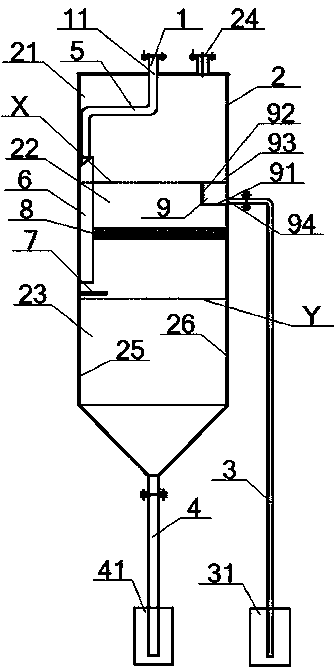
[0054] see figure 1 , a solvent separation device for evaporating and recovering a solvent system, comprising a cylinder body 2, a feed pipe 1, an organic phase discharge pipe 3, an aqueous phase discharge pipe 4, a transition pipe 5, a condensate vertical conduit 6, a condensate Liquid level guide plate 7, metal phase separation net 8 and organic phase overflow tank 9;

[0055] An air cavity 21, an organic phase cavity 22, and a water cavity 23 are sequentially arranged in the cylinder body 2 along the direction from the feed port 11 to the water phase discharge pipe 4, and a liquid cavity is formed at the junction of the air cavity 21 and the organic phase cavity 22. The bit line X, the junction of the organic phase chamber 22 and the water chamber 23 form a two-phase line Y, the top of the air chamber 21 communicates with the feed port 11 and the vent pipe 24, and the side of the organic phase chamber 22 passes through the organic phase The discharge pipe 3 communicates wi...

Embodiment 2

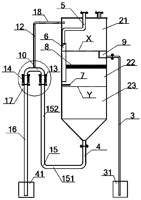
[0061] see figure 2 , the basic content is the same as in Example 1, the difference is that:

[0062] One end of the water phase discharge pipe 4 communicates with the bottom of the cylinder body 2, the other end communicates with the right end of the horizontal section 151 on the L-shaped pipe 15, and the left end of the horizontal section 151 communicates with the bottom end of the vertical section 152 on the L-shaped pipe 15. Connected, the horizontal section 151 and the vertical section 152 are vertically connected, and the top of the vertical section 152 communicates with the water phase receiving tank 41 after passing through the inverted Y-shaped pipe 17. Specifically, the top of the vertical section 152 passes through the No. 1 height-adjustable type The flexible pipe 13 communicates with the liquid inlet end of the inverted U-shaped pipe 10, and the liquid outlet end of the inverted U-shaped pipe 10 communicates with the water phase receiving tank 41 after passing th...


PUM


Abstract

The invention provides a solvent separating unit used for evaporation and recovery of a solvent system. A feed pipe arranged at the top of a barrel included by the solvent separating unit is communicated with a vertical condensate conduit through a transition pipe; the lower part of the vertical condensate conduit is provided with a horizontal condensate guide plate which is arranged to be slightly higher than a two-phase line; the central part of the vertical condensate conduit penetrates a metal phase-splitting mesh; an organic phase overflow groove with an upper opening is arranged above the metal phase-splitting mesh; and the top of the organic phase overflow groove is aligned with a liquid level line. In usage, a condensate successively flows through the transition pipe, the vertical condensate conduit and the horizontal condensate guide plate and then into the barrel for phase splitting; a water phase flows into a water phase discharging pipe, and an organic phase successively flows through the metal phase-splitting mesh and the organic phase overflow groove and then into an organic phase discharging pipe; and an inverted Y-shaped pipe can be arranged out of the barrel so as to adjust the two-phase line and prevent siphonage. According to the invention, the solvent separating unit has the advantages of an improved phase splitting effect, an improved phase splitting speed, a simple structure, convenience in operation, a wide application scope and capacity of preventing siphonage.

Description

technical field [0001] The invention relates to the technical field of solvent separation, in particular to a solvent separation device for evaporating and recovering a solvent system and its use method, which is specifically suitable for improving the separation effect and speed of organic phase and aqueous phase mixed liquid, and has a simple structure and easy operation . Background technique [0002] In the general solvent recovery system, the method of stripping or azeotropic distillation is generally used to recover the solvent, and a rectification column is also used. The extractant used in the solvent extraction process is mostly a combination of various solvents. After completing an extraction, washing, and stripping process, the extractant can be reused for the next same process and recycled. During such an extraction process, part of the extractant will be dissolved in the liquid to be extracted (usually an aqueous solution). In order to reduce production costs, ...

Claims


Application Information

Patent Timeline
Patent Type & Authority Applications(China)
IPC IPC(8): B01D17/02
Inventor 吴杰
Owner 吴杰
Why Eureka
Try Eureka