Current-assisted titanium alloy bellows hot-forming tool and method
A corrugated tube and titanium alloy technology, applied in the field of corrugated tube thermoforming molds, can solve problems such as heat loss, achieve the effects of improving plastic deformation capacity, uniform temperature distribution, improving energy utilization and heating efficiency
- Summary
- Abstract
- Description
- Claims
- Application Information
AI Technical Summary
Problems solved by technology
Method used
Image
Examples
specific Embodiment approach 1
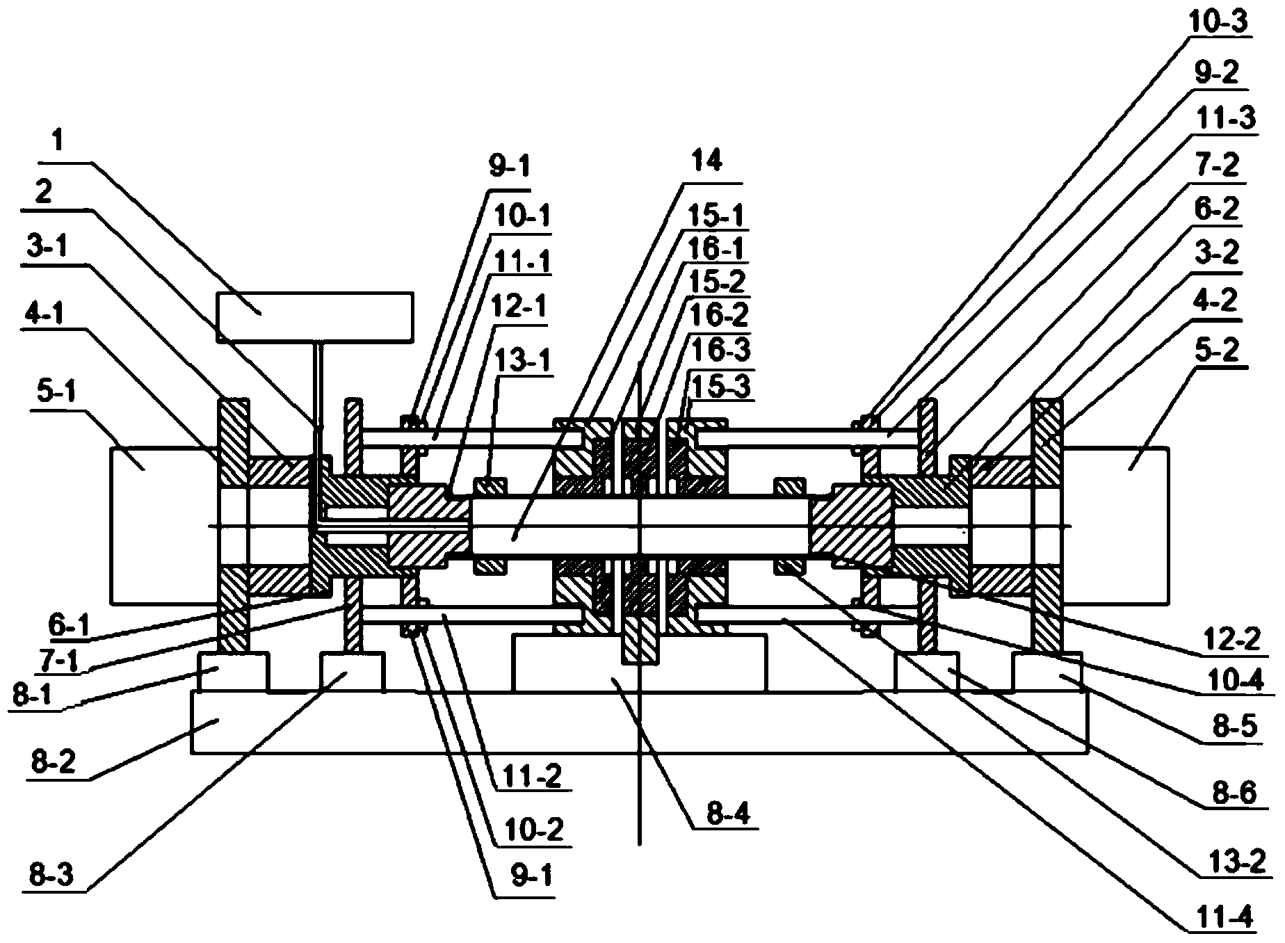
[0022] Specific Embodiment 1: In this embodiment, the current-assisted titanium alloy bellows thermoforming mold includes an argon gas cylinder 1, a gas pipe 2, a right axial loading shaft 3-2, a left axial loading shaft 3-1, and a left axial loading device for fixing Plate 4-1, right axial loading device fixing plate 4-2, left cylinder 5-1, right cylinder 5-2, left axial loading sleeve 6-1, right axial loading sleeve 6-2, left sleeve Tube support plate 7-1, right sleeve support plate 7-2, first workbench 8-1, second workbench 8-2, third workbench 8-3, fourth workbench 8-4, fifth workbench Workbench 8-5, sixth workbench 8-6, left positioning plate 9-1, right positioning plate 9-2, first positioning nut 10-1, second positioning nut 10-2, third positioning nut 10- 3. The third and fourth positioning nuts 10-4, the first positioning stud 11-1, the second positioning stud 11-2, the third positioning stud 11-3, the fourth positioning stud 11-4, the left seal Device 12-1, right sea...
specific Embodiment approach 2
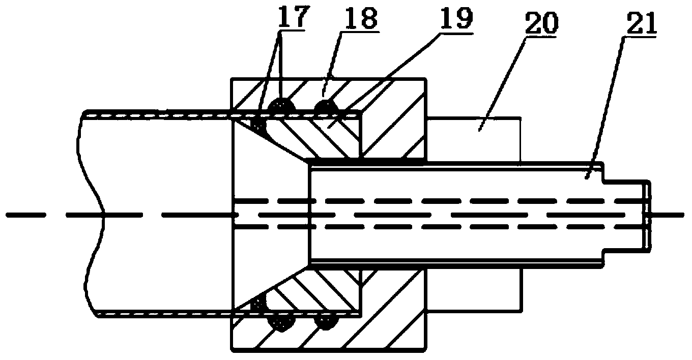
[0029] Embodiment 2: The difference between this embodiment and Embodiment 1 is that the left sealing device 12-1 and the sealing device 12-2 include a rubber ring 17, a fastening ring 18, a copper plug ring 19, a nut 20 and a bolt 21 , which is characterized in that the bolt 21 is screwed with the nut 20, two rubber rings 17 are arranged on the surface of the inner hole of the fastening ring 18, the copper plug ring 19 is screwed on the inner end of the bolt 21, and the fastening ring 18 is located on the copper plug ring 19 and nut 20 between. Others are the same as in the first embodiment.
specific Embodiment approach 3
[0030] Specific implementation mode three: In this implementation mode, the current-assisted hot forming method of titanium alloy bellows is as follows:
[0031] The first ceramic mold 16-1, the second ceramic mold 16-2, and the third ceramic mold 16-3 are embedded in the first metal mold frame 15-1, the second metal mold frame 15-2, and the third metal mold frame 15 In -3, the metal mold frame 15-1, the second metal mold frame 15-2, and the third metal mold frame 15-3 have cavities, the diameter of which is the same as that of the pipe blank 14, and the first ceramic Surfaces where the mold 16-1, the second ceramic mold 16-2, and the third ceramic mold 16-3 are in contact with the first metal mold frame 15-1, the second metal mold frame 15-2, and the third metal mold frame 15-3 Boron nitride is coated on the top after being polished, and the tube blank 14 passes through the cavities of the first ceramic mold 16-1, the second ceramic mold 16-2, and the third ceramic mold 16-3,...
PUM
 Abstract
Description
Claims
Application Information
 - R&D
- Intellectual Property
- Life Sciences
- Materials
- Tech Scout
- Unparalleled Data Quality
- Higher Quality Content
- 60% Fewer Hallucinations
Browse by: Latest US Patents, China's latest patents, Technical Efficacy Thesaurus, Application Domain, Technology Topic, Popular Technical Reports.
© 2025 PatSnap. All rights reserved.Legal|Privacy policy|Modern Slavery Act Transparency Statement|Sitemap|About US| Contact US: help@patsnap.com


