Integrated water heating floor block and heat conducting component thereof

A technology for heat-conducting components and floorboards, applied in the field of building decoration, can solve the problems of difficult implementation, poor reliability of heat storage and slow-release composite floor modules, and large distances.

Inactive Publication Date: 2014-01-22
江苏德威木业有限公司
View PDF13 Cites 2 Cited by
  • Summary
  • Abstract
  • Description
  • Claims
  • Application Information

AI Technical Summary

Problems solved by technology

In the floor heating technology with the above structure, the heat generated by the heat conduction element needs to be conducted from bottom to top to the bonding material and the floor decoration material in sequence, and a large amount of heat is absorbed by the bond material and the floor decoration material, resulting in waste of energy; secondly, due to the distance between the heat conduction elements The distance between the laid ground (that is, the decorative surface of the ground decoration material) is relatively large, resulting in a slow process of heat transfer to the indoor space
Third, once there are quality problems such as water leakage during use, it is impossible to find the problem point. Even if it is found, it will be very troublesome to repair. Adhesive materials and floor finishes, resulting in costly repairs
"First of all, there are many sizes and specifications of floor tiles, and the small ones are 30×30 cm. If coils are installed on floor tiles of this size, it will be more difficult to process, resulting in increased production costs; secondly, by other figure 2 It can be seen that the pipe joint part, that is, the connecting piece 5 in the manual, is exposed. When in use, it will be stepped on frequently, which will easily cause it to fall off or loosen, affecting normal use.
In addition, exposed pipe joints can also create obstac

Method used


Image

  • Integrated water heating floor block and heat conducting component thereof
  • Integrated water heating floor block and heat conducting component thereof
  • Integrated water heating floor block and heat conducting component thereof

Examples


Embodiment 1

[0106] (Example 1, heat conducting member)

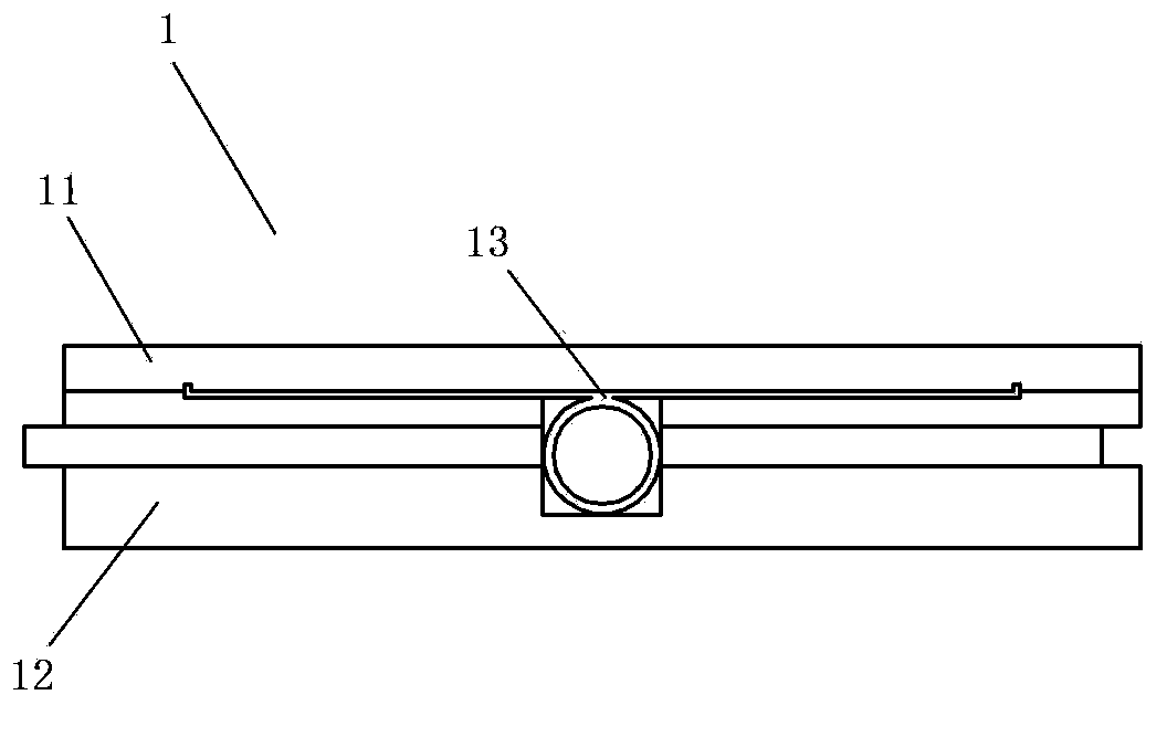
[0107] See Figure 9 and Figure 10, the heat conduction member 13 is an integral piece made of metal material, or is a glass fiber reinforced plastic profile, or an extruded profile made of plastic with a polymer material as the main component. In this embodiment, it is an aluminum alloy profile. The heat conducting member 13 includes a pipe part 13-1, a heat dissipation part 13-2 and a positioning part 13-3. The pipe part 13-1 is a linear pipe arranged along the front and back directions, and the inner wall of the pipe part 13-1 is sprayed with anti-corrosion paint; the heat dissipation part 13-2 is in the shape of a flat plate as a whole, and the heat dissipation part 13-2 is a direct heat dissipation part . The heat dissipation part 13-2 is connected to the duct part 13-1 from above. There are two positioning parts 13-3, which are respectively located on the left and right sides of the upper part of the heat dissipation part...

Embodiment 2

[0108] (Example 2, heat conducting member)

[0109] See Figure 11 , the rest of this embodiment is the same as that of Embodiment 1, and the heat conduction member 13 is still an aluminum alloy profile. to the through hole. Each heat soaking hole 13-4 is symmetrically arranged on the left and right sides of the heat dissipation part 13-2 with respect to the vertical plane passing through the axis of the pipe part 13-1 to form a left heat soaking hole group 13-4a and a right heat soaking hole Group 13-4b. The soaking holes 13-4 in each soaking hole group are arranged in different rows in the left and right directions, and the soaking holes 13-4 in each row are arranged at equal intervals along the front and rear directions, and the soaking holes in the same row The hole diameters of 13-4 are equal, and between the heat soaking holes 13-4 of adjacent rows, the hole diameter of the heat soaking holes 13-4 located in the left and right inner rows is larger than the hole diamet...

Embodiment 3

[0110] (Example 3, heat conducting member)

[0111] See Figure 13 to Figure 16 , the rest of this embodiment is the same as that of Embodiment 1, and the heat conduction member 13 is still an aluminum alloy profile. The difference is that the heat conduction member 13 of this embodiment is also equipped with a corresponding plug 14 and the following different technical features .

[0112] See Figure 18 and Figure 19 The heat dissipation part 13-2 of the heat conducting member 13 is divided into two heat dissipation parts, which are respectively located on the left and right sides of the pipe part 13-1. The structural shapes of the two heat dissipation parts are the same, and the two heat dissipation parts are divided into a left heat dissipation part 13-2a and a right heat dissipation part 13-2b according to their left and right positions. The two heat dissipation parts are both in the shape of a square tube, and the two heat dissipation parts are heat-gathering and hea...


PUM

PropertyMeasurementUnit
Lengthaaaaaaaaaa
Lengthaaaaaaaaaa
Diameteraaaaaaaaaa

Abstract

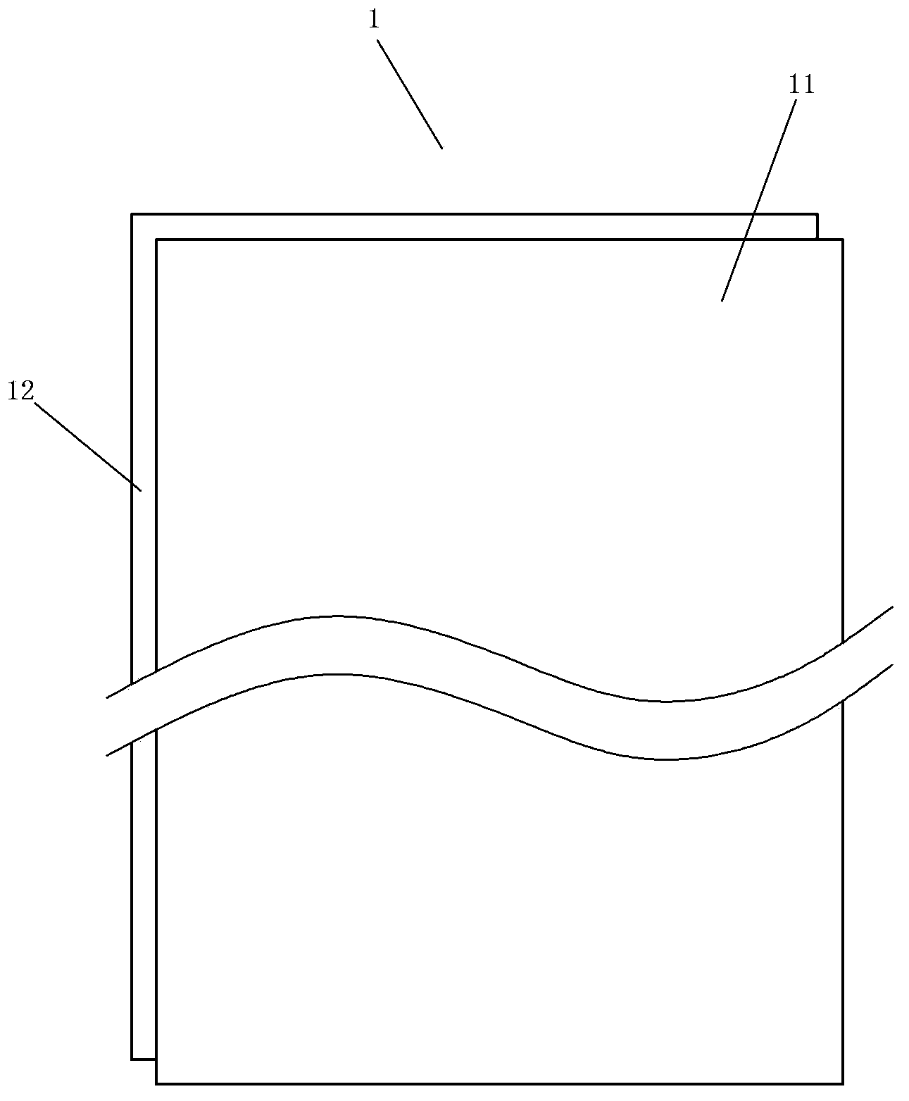
The invention discloses an integrated water heating floor block. The periphery of the floor block is provided with inserting portions. The integrated water heating floor block is characterized in that the whole floor block is of a flat rectangular shape and comprises a decoration surface, a lower portion body and a heat conducting component. The inserting portion of each side of the floor block is arranged on the lower portion body. The heat conducting component comprises a pipeline portion and a heat dissipating portion. The pipeline portion is a linear pipeline arranged in the forward and backward direction. The heat dissipating portion is connected with the pipeline portion. The length of the heat conducting component in the forward and backward direction is slightly smaller than the length of the floor block with the inserting portions at the front side and the rear side removed in the forward and backward direction. The lower portion body is further provided with an installation groove enabling the front portion and the rear portion of the lower portion body to be communicated. The installation portion comprises a pipe groove portion. The pipeline portion of the heat conducting component is located in the pipe groove portion of the lower portion body. The heat conducting component adheres to and is fixed to the corresponding portion of the upper side face of the lower portion body through the lower side face of the heat dissipating portion of the heat conducting component and the decoration surface adheres to and is fixed to the corresponding portion of the upper side face of the lower portion body and the upper side face of the head dissipating portion of the heat conducting component through the corresponding portion of the lower side face of the decoration surface.

Description

technical field [0001] The invention relates to a product in the field of building decoration, in particular to an integrated water heating floor board and a heat conducting component thereof. Background technique [0002] The traditional heating in northern my country adopts centralized heating, and the pipes in the room are connected to the radiators for heating and heating. However, the convection of indoor hot air is likely to cause dust floating and air drying. The water supply temperature of the radiator group is 70-85 ℃, high energy consumption, low thermal efficiency, uneven indoor temperature, low surface temperature, and poor comfort. The radiator group needs to occupy a certain space and affects the appearance. [0003] Floor heating means that the heat medium liquid (usually water, or heat transfer oil) circulates in the disc-shaped pipes under the floor. The floor is mainly radiated, supplemented by conduction and convection to transfer heat to the room, so as...

Claims


Application Information

Patent Timeline
IPC IPC(8): F24D3/12E04F15/02
Inventor 葛林葛鑫琰
Owner 江苏德威木业有限公司
Why Eureka
Try Eureka