On-line fatigue crack detecting system and on-line fatigue crack detecting method

A fatigue crack detection system technology, applied in measurement devices, material analysis using acoustic wave emission technology, material analysis by optical means, etc., can solve problems such as low measurement accuracy, low detection automation, and vulnerability to human factors. , to achieve the effect of improving accuracy and reliability

Active Publication Date: 2014-01-22
TIANJIN ENG MACHINERY INST
View PDF3 Cites 40 Cited by
  • Summary
  • Abstract
  • Description
  • Claims
  • Application Information

AI Technical Summary

Problems solved by technology

Visual inspection methods include visual inspection, penetration inspection technology, magnetic particle inspection technology, etc. Among them, the visual inspection method is the most traditional method. When the fatigue load amplitude is large and the loading frequency is high, there is a problem that it is difficult to read during the test, and the machine needs to be shut down. Measurement, the measurement accuracy is low, it is easily affected by human factors, and if you want to realize real-time online observation, you need to use more manpower; penetration detection technology can only detect the surface opening macroscopic defects of dense metals, and the cracks that penetrate into the crack Penetrants and dyes are difficult to clean, the monitoring process is cumbersome, and online monitoring cannot be realized; magnetic particle inspection technology can only be used to detect defects on the surface or near the surface of ferromagnetic materials, which requires shutdown for inspection, and real-time inspection cannot be realized. The inspection process is also cumbersome
Indirect nondestructive testing methods mainly include ultrasonic testing technology, eddy current testing technology, metal magnetic memory testing technology, acoustic emission testing technology, etc. Ultrasonic testing technology is currently a detection method with high quantitative detection accuracy and reliability, but it is also difficult to achieve dynamic real-time detection , and the degree of detection automation is low; eddy current detection is easily affected by the external magnetic field, and can only detect ferromagnetic materials, and the detection depth is only 2-3mm; metal magnetic memory detection technology is a non-destructive testing technology that has emerged in recent years. Detecting the distribution of stress concentration in the early stage of ferromagnetic components, the research on the quantitative detection of crack size is still in its infancy, and even its mechanism research is not mature enough
In the above methods, it is necessary to stop the machine or even cut the sample before testing. It is difficult to realize the online, real-time and dynamic detection of crack initiation and growth process and fatigue damage evaluation in the whole process, and the detection form is relatively simple.
[0004] Acoustic emission technology is a high-sensitivity online non-destructive testing technology. Acoustic emission signals (count, effective value, signal strength, etc.) are sensitive to the initiation and propagation of cracks. The main advantage is the realization of dynamic real-time detection. The disadvantage is that there are still some difficulties in quantitative detection of crack initiation and expansion size, and it is only detected indirectly through the damage signal released by crack initiation and expansion, and cannot be intuitively detected in the form of images. Real-time detection of the whole process of crack initiation, propagation and fracture

Method used


Image

  • On-line fatigue crack detecting system and on-line fatigue crack detecting method
  • On-line fatigue crack detecting system and on-line fatigue crack detecting method
  • On-line fatigue crack detecting system and on-line fatigue crack detecting method

Examples


Embodiment Construction

[0038] In order to further understand the invention content, characteristics and effects of the present invention, the following examples are given, and detailed descriptions are as follows in conjunction with the accompanying drawings:

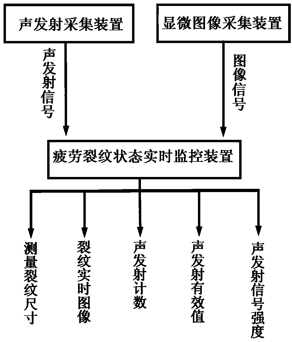
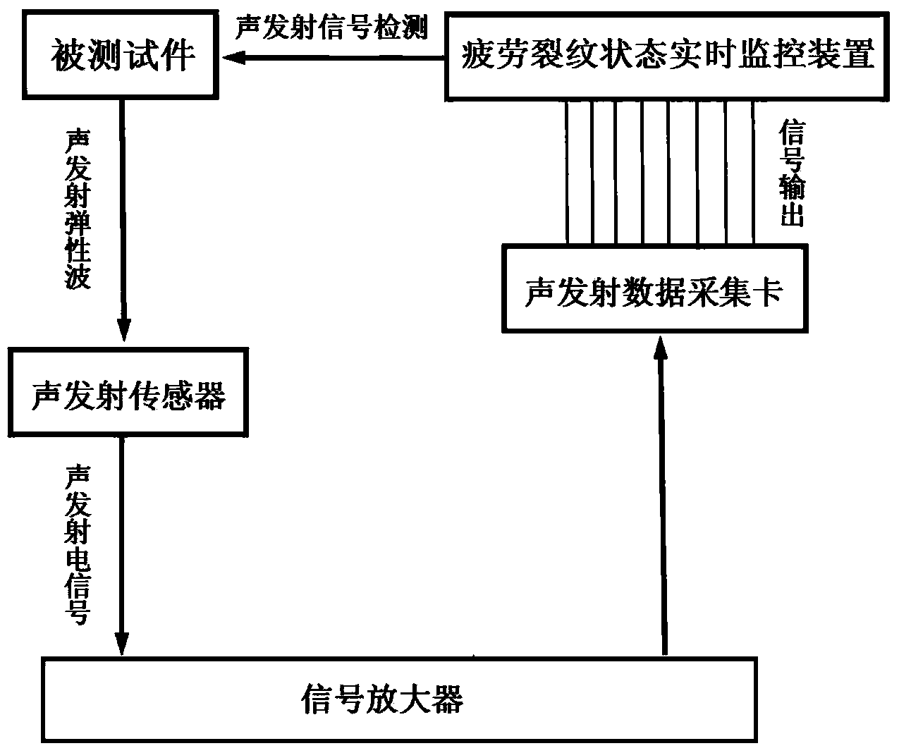
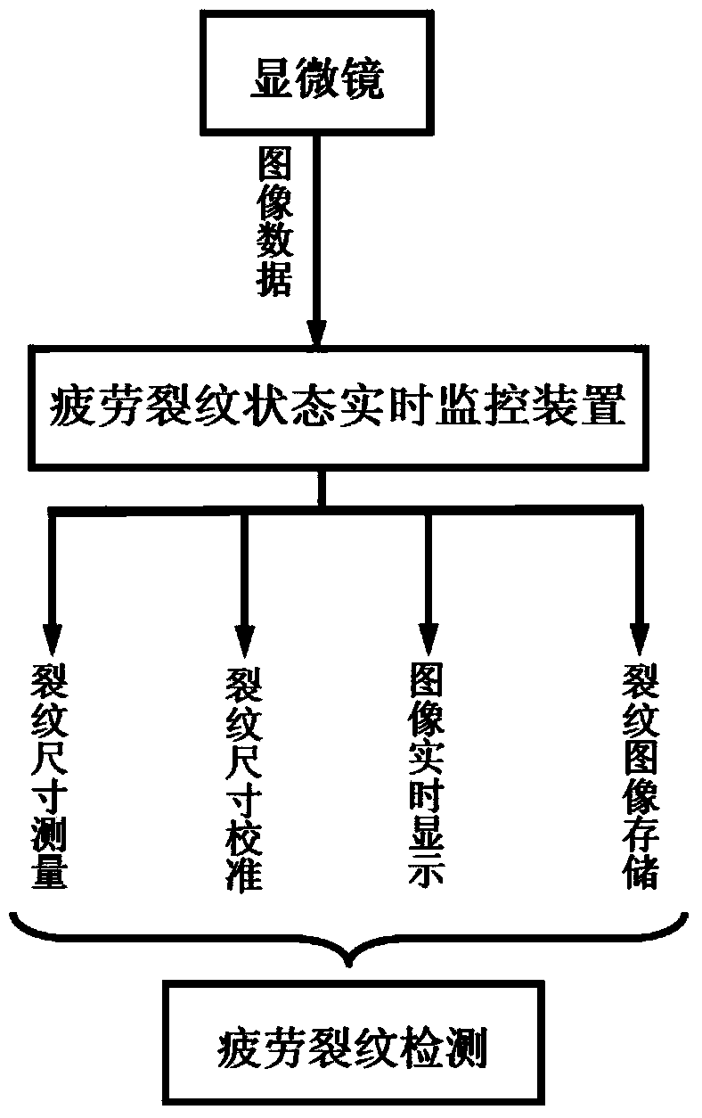
[0039] See Figure 1 to Figure 9 , an on-line detection system for fatigue cracks, comprising an acoustic emission acquisition device, a microscopic image acquisition device and a real-time monitoring device for the state of fatigue cracks, the acoustic emission acquisition device and the microscopic image acquisition device are respectively connected to the real-time status of the fatigue crack Signals are transmitted between the monitoring devices, the acoustic emission acquisition device collects the acoustic emission signals of fatigue crack initiation and expansion release in real time, the microscopic image acquisition device collects image signals of the fatigue crack state in real time, and the fatigue crack state real-time monitoring ...


PUM


Abstract

The invention discloses an on-line fatigue crack detecting system. The detecting system comprises an acoustic emission collecting device, a microscopic-image collecting device and a real-time fatigue crack state monitoring device. The acoustic emission collecting device collects acoustic emission signals of fatigue crack initiation and extension and release in real time. The microscopic-image collecting device collects image signals of fatigue crack states in real time. The real-time fatigue crack state monitoring device receives the signals from the acoustic emission collecting device and signals from the microscopic-image collecting device. A real-time fatigue crack state monitoring software, which is used to process the received signals and generates acoustic emission characteristic parameters, images and crack dimension data of a fatigue crack changing process, is disposed in the real-time fatigue crack state monitoring device. The invention also provides an on-line fatigue crack detecting method. The detecting system and the detecting method can achieve on-line dynamic real-time detection of fatigue crack initiation and extension.

Description

technical field [0001] The invention relates to a fatigue crack detection system and detection method, in particular to an online fatigue crack detection system and detection method. Background technique [0002] At present, fatigue is one of the main reasons for the failure of various components of construction machinery. The long-term action of cyclic loads leads to crack initiation and propagation until fracture is the main mechanism and process of fatigue failure. Fatigue failure is sudden, and it often fails suddenly when it is in service under the safety factor, causing immeasurable losses. Therefore, how to accurately and reliably detect the initiation and growth of fatigue cracks online in real time is crucial to establishing an accurate and reliable fatigue life prediction model and preventing sudden damage to mechanical equipment. [0003] The existing fatigue crack detection methods mainly include visual detection method and indirect nondestructive detection meth...

Claims


Application Information

Patent Timeline
Patent Type & Authority Applications(China)
IPC IPC(8): G01N29/14G01N21/84
Inventor 张志强张国胜刘艳芳王军威吴鸿雁李长茂
Owner TIANJIN ENG MACHINERY INST
Why Eureka
Try Eureka