
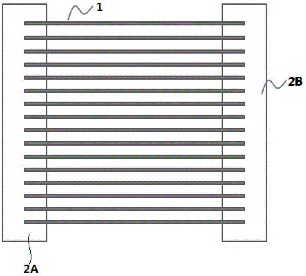
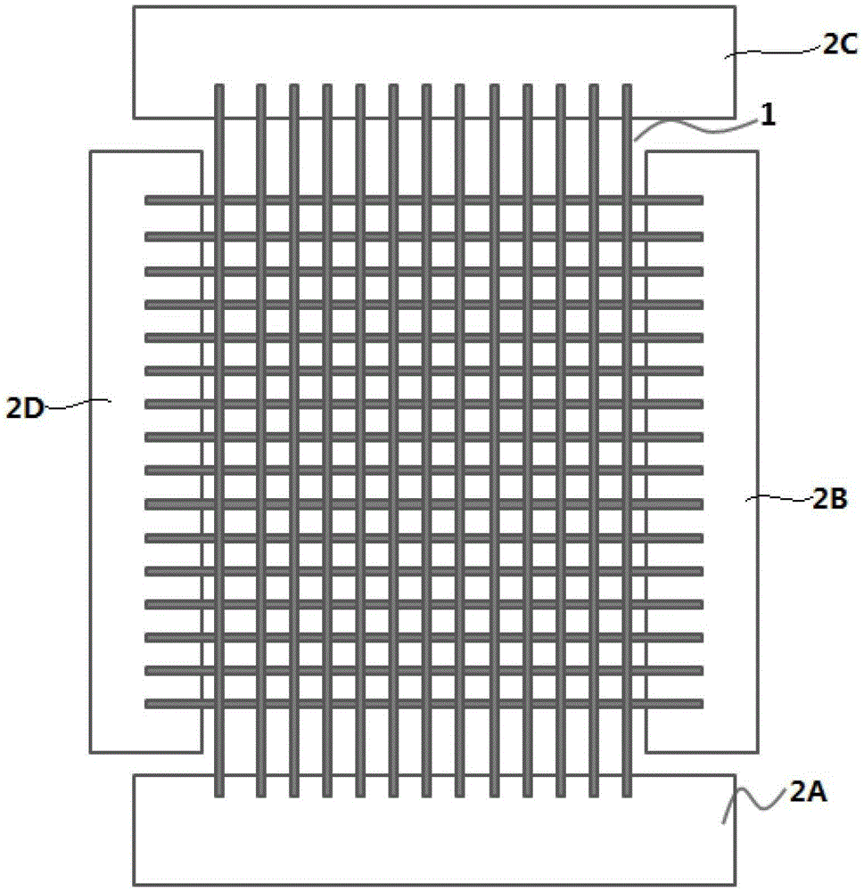
a field emission tube

A technology of field emission tube and carbon tube fiber, which is applied in the direction of X-ray tube electrodes and X-ray tube components, etc., can solve the problems of complex process, grid melting deformation, expensive production cost, etc., and achieve high axial thermal conductivity , Simplified manufacturing process, high mechanical strength

Active Publication Date: 2016-04-27
SHANGHAI UNITED IMAGING HEALTHCARE
View PDF7 Cites 0 Cited by
  • Summary
  • Abstract
  • Description
  • Claims
  • Application Information

AI Technical Summary

Problems solved by technology

Among them, the gate is usually made of metals such as W or Mo with a high melting point, but due to the impact of strong electron flow, it is still difficult for the gate of W and Mo to avoid evaporation caused by high temperature and the sputtering effect of the electron beam on the metal.
For many applications that require high current, the gate is often melted and deformed due to high heat, and the vacuum environment will also be severely damaged by the evaporation and sputtering of the gate material, which will seriously affect the field emission performance, resulting in Reduced lifetime of field emission electronics
In addition, traditional gates require the use of semiconductor planar technology or precision machining, which requires complex processes and high manufacturing costs. At the same time, it is difficult to guarantee the quality of the final synthesized gate, which affects the use of

Method used


Image

  • a field emission tube
  • a field emission tube
  • a field emission tube

Examples


Embodiment Construction

[0013] The field emission X-ray tube of the present invention will be further described in detail below.

[0014] The existing field emission X-ray tubes all include a cathode, an anode and a grid, wherein the grid includes a bracket and carbon tube fibers connected to the bracket. Because carbon nanotubes, the material of carbon tube fibers, have large specific surface area, high thermal stability (remains stable at 3400°C), high mechanical strength, high axial thermal conductivity (about 3500W / (m.K) and good electrical conductivity. Become a potential heat dissipation conductive material. People have carried out extensive research on carbon tubes and proved that they have excellent thermal conductivity (Nanotechnology, 2000, 11, 65; Physical Review B, 2002, 66, 165440). As a heat dissipation device Applied research has also made some progress, such as CN102318438A uses carbon nanotube ink as a printed heat dissipation material, CN201110207615.8 reports a LED lamp that uses c...


PUM


Abstract

The invention provides a field-emission tube comprising a cathode, an anode and a gate. The gate comprises a support and a carbon tube fiber connected to the support. The gate is made of the carbon tube fiber, so that durability and service life of the gate of the field-emission X-ray tube is improved greatly.

Description

technical field [0001] The invention relates to a field emission electronic device, in particular to a field emission X-ray tube of a novel carbon tube fiber grid. Background technique [0002] Existing field emission electronic devices mostly adopt a triode structure of cathode, grid and anode. Among them, the gate is usually made of metals such as W or Mo with a high melting point. However, due to the impact of strong electron currents, it is still difficult for the gate of W and Mo to avoid evaporation caused by high temperature and the sputtering effect of the electron beam on the metal. For many applications that require high current, the gate is often melted and deformed due to high heat, and the vacuum environment will also be severely damaged by the evaporation and sputtering of the gate material, which will seriously affect the field emission performance, resulting in The lifetime of field emission electronic devices is reduced. In addition, the traditional gate n...

Claims


Application Information

Patent Timeline
Patent Type & Authority Patents(China)
IPC IPC(8): H01J35/04
Inventor 李冬松刘红林章健
Owner SHANGHAI UNITED IMAGING HEALTHCARE
Learn More