Equipment and method for thermal removing of paint layers of waste metals
A waste metal and paint layer technology, applied in the field of circular economy technology and environmental protection, can solve the problems of poor working environment, low treatment efficiency, serious paint dust, etc., and achieve high paint stripping efficiency, good environment and economic benefits, and uniform heating. Effect
- Summary
- Abstract
- Description
- Claims
- Application Information
AI Technical Summary
Problems solved by technology
Method used
Image

Examples
example 1
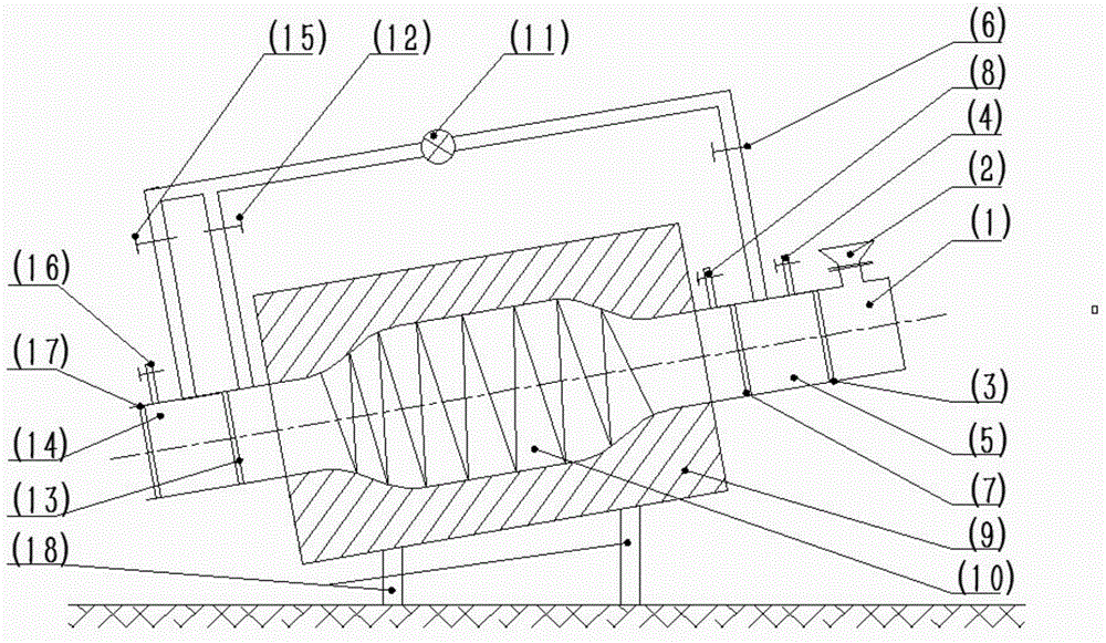
[0027] Open gate valve 1 (3) and gate valve 2 (7), put the crushed waste aluminum cans into the furnace tube (10) through the feed port (2) and feed bin (1), and start the furnace Pipe (10) rotates and heats the switch, controls the inclination angle of 0°, the speed of 0rad / min, and dries at 140°C for 30 minutes; after the drying is completed, close valve 2 (6), gate valve 2 (7), and valve 3 ( 8), gate valve 3 (13) and valve 5 (15), turn on the mechanical pump (11) and valve 4 (12) for vacuuming; when the pressure of the furnace tube (10) is lower than 200Pa, turn off the mechanical pump (11 ) and valve 4 (12), open valve 3 (8) to fill the furnace tube (10) with a controlled atmosphere, and the oxygen partial pressure is 0 atm; keep the furnace tube (10) at a speed of 0 rad / min, and increase the temperature at a rate of 5 °C / min. Heat the furnace tube (10) to 240°C for 90 minutes of thermal paint removal; after the paint removal is complete, close the valve 3 (8), open the ga...
example 2
[0029]Open gate valve 1 (3) and gate valve 2 (7), put the crushed waste aluminum cans into the furnace tube (10) through the feed port (2) and feed bin (1), and start the furnace Rotate the tube (10) and heat the switch, control the inclination angle to 10°, the speed to 5rad / min, and dry at 120°C for 5 minutes; after drying, close valve 2 (6), gate valve 2 (7), and valve 3 ( 8), gate valve 3 (13) and valve 5 (15), turn on the mechanical pump (11) and valve 4 (12) for vacuuming; when the pressure of the furnace tube (10) is lower than 200Pa, turn off the mechanical pump (11 ) and valve 4 (12), open valve 3 (8) to fill the furnace tube (10) with a controlled atmosphere, and the oxygen partial pressure is 0 atm; keep the furnace tube (10) at a speed of 5 rad / min, and increase the temperature at a rate of 8 °C / min. Heat the furnace tube (10) to 300°C for 60 minutes of thermal stripping; after the paint stripping is completed, close the valve 3 (8), open the gate valve 3 (13), rev...
example 3
[0031] Open gate valve 1 (3) and gate valve 2 (7), put the crushed waste aluminum cans into the furnace tube (10) through the feed port (2) and feed bin (1), and start the furnace Pipe (10) rotates and heats the switch, controls the inclination angle of 15°, the rotation speed of 10rad / min, and performs drying at 100°C for 10 minutes; after drying, close valve 2 (6), gate valve 2 (7), and valve 3 ( 8), gate valve 3 (13) and valve 5 (15), turn on the mechanical pump (11) and valve 4 (12) for vacuuming; when the pressure of the furnace tube (10) is lower than 200Pa, turn off the mechanical pump (11 ) and valve 4 (12), open valve 3 (8) to fill the furnace tube (10) with a controlled atmosphere, the oxygen partial pressure is 0.04atm; keep the furnace tube (10) at a speed of 10rad / min, and heat up at a rate of 10°C / min Heat the furnace tube (10) to 400°C for 45 minutes of thermal stripping; after the paint stripping is completed, close the valve 3 (8), open the gate valve 3 (13), ...
PUM
 Abstract
Description
Claims
Application Information
 - R&D
- Intellectual Property
- Life Sciences
- Materials
- Tech Scout
- Unparalleled Data Quality
- Higher Quality Content
- 60% Fewer Hallucinations
Browse by: Latest US Patents, China's latest patents, Technical Efficacy Thesaurus, Application Domain, Technology Topic, Popular Technical Reports.
© 2025 PatSnap. All rights reserved.Legal|Privacy policy|Modern Slavery Act Transparency Statement|Sitemap|About US| Contact US: help@patsnap.com