Drum type machine tool

A drum-type and drum-wheel technology, which is applied in the direction of metal processing machinery parts, clamping, support, etc., can solve the problems of unstable processing quality, large floor space, low efficiency, etc., and achieve the improvement of processing quality stability, occupying Effect of reduced land area and increased efficiency

Active Publication Date: 2015-09-16
CHANGZHOU XIAOGUO INFORMATION SERVICES
View PDF5 Cites 0 Cited by
  • Summary
  • Abstract
  • Description
  • Claims
  • Application Information

AI Technical Summary

Problems solved by technology

[0003] The technical problem to be solved by the present invention is to provide a drum-type machine tool, which solves the problems of low efficiency, unstable processing quality, high energy consumption and large occupied area in traditional processing.

Method used


Image

  • Drum type machine tool
  • Drum type machine tool
  • Drum type machine tool

Examples


Embodiment Construction

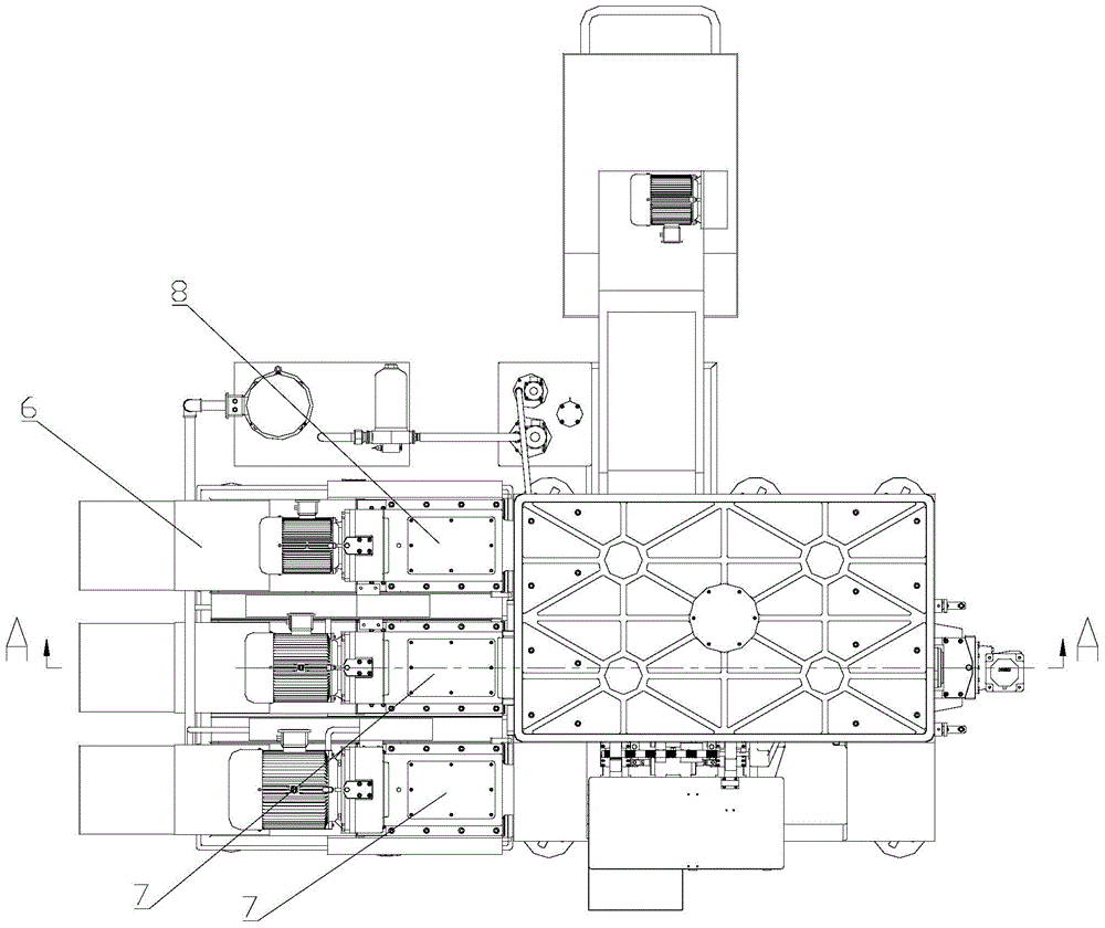
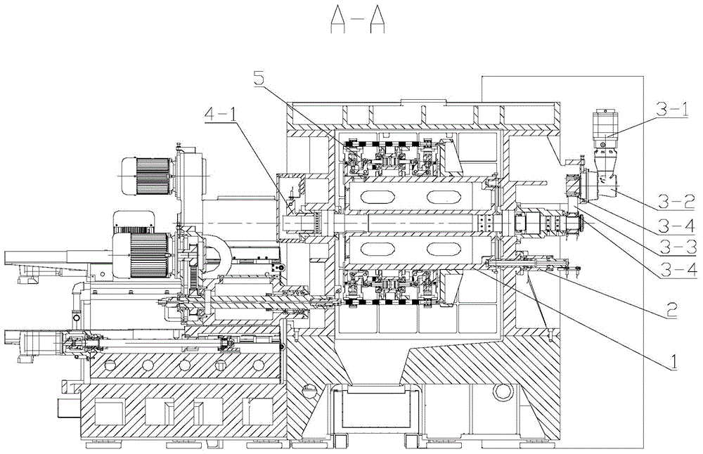
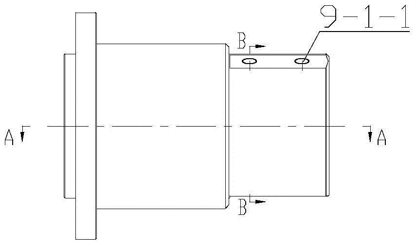
[0033] Such as figure 1 and 2 As shown, a drum-type machine tool includes a frame, a CNC machining unit, a CNC slide table, a drum, a hydraulic clamp 5, a hydraulic clamping distributor, an indexing drive mechanism, a positioning mechanism and a drum clamping mechanism, and the drum The wheel 1 is installed on the frame through the drum shaft 1-1. There are multiple stations on the drum 1, and a hydraulic clamp 5 is arranged on each station. The indexing drive mechanism and the positioning mechanism are located on the same side of the drum 1. The drum 1 The clamping mechanism is located on the other side of the drum 1 . The frame includes left and right wall panels on both sides of the drum, and a fixed beam at the top of the left and right wall panels connecting the left and right wall panels. The CNC slide table 6 is installed on the frame, and the CNC processing unit includes two CNC drilling processing units 7 and a CNC chamfering processing unit 8. The CNC drilling proc...


PUM


Abstract

The invention relates to a drum wheel machine tool, which comprises a rack, a numerical control machining unit, a numerical control sliding table, a drum wheel, hydraulic clamps, a hydraulic clamping distributor, an indexing driving mechanism, a positioning mechanism and a drum wheel clamping mechanism; the shaft end of a drum wheel shaft is provided with the hydraulic clamping distributor; an oil path penetrates through the drum wheel shaft and the drum wheel to supply oil to the hydraulic clamps; the indexing driving mechanism drives the drum wheel to rotate to each station; the positioning mechanism comprises a positioning oil cylinder mounted on the rack and a positioning hole in the side surface of the drum wheel; a piston rod of the positioning oil cylinder extends to be inserted into the positioning hole in the side surface of the drum wheel and position the drum wheel; the drum wheel clamping mechanism pushes the drum wheel shaft to move along the axial direction, so the drum wheel is abutted against on the rack, and the drum wheel is clamped; the numerical control sliding table is mounted on the rack; the numerical control machining unit is mounted on the numerical control sliding table for feeding. The drum wheel machine tool has the beneficial effects that the efficiency is increased by 4-5 times, the machining quality stability of a machined part is obviously improved, the energy consumption is reduced by a half, and the occupation area is reduced by more than 5 times.

Description

technical field [0001] The invention relates to a drum type machine tool. Background technique [0002] The conventional method of drilling the end face of the slender shaft is to use a lathe, clamp the workpiece in the chuck, install the twist drill on the tailstock or fix it on the carriage, and manually feed the tailstock sleeve or The longitudinal carriage is fed manually (or automatically) to complete the machining of the hole. The shortcoming of this conventional processing mode is: 1, efficiency is low. In the case of mass production, it is often necessary to use dozens of operators to work at the same time, which greatly increases the cost of human resources and brings difficulties in management; 2. The processing quality is unstable. Since the workpieces are manually clamped in the three-jaw chuck of the lathe, the clamping force of each clamping cannot be consistent, the clamping force of each operator cannot be consistent, and the feed speed during processing ca...

Claims


Application Information

Patent Timeline
Patent Type & Authority Patents(China)
IPC IPC(8): B23P23/02B23Q7/02B23Q3/08
CPCB23P23/02B23Q3/082B23Q7/02B23Q16/06
Inventor 夏晓平杨春宏邱国仙张在平
Owner CHANGZHOU XIAOGUO INFORMATION SERVICES
Why Eureka
Try Eureka