Air compression/hydraulic punching machine

A technology of hydraulic press and nitrogen, applied in the fields of hydraulic press and steam, can solve the problems of high mechanical noise, cracked bed, scrapped press, etc., and achieve the effects of low mechanical noise, low steel consumption and low manufacturing cost.

Inactive Publication Date: 2014-02-05
LIAOCHENG UNIV
View PDF8 Cites 9 Cited by
  • Summary
  • Abstract
  • Description
  • Claims
  • Application Information

AI Technical Summary

Problems solved by technology

This type of punching machine has a lot of consumables, is heavy, and has a lot of mechanical noise
Once overloaded during work, it is easy to cause the bed to crack and make the punching machine scrapped

Method used


Image

  • Air compression/hydraulic punching machine
  • Air compression/hydraulic punching machine
  • Air compression/hydraulic punching machine

Examples


Embodiment Construction

[0011] Specific embodiments of the present invention will be described below in conjunction with the accompanying drawings.

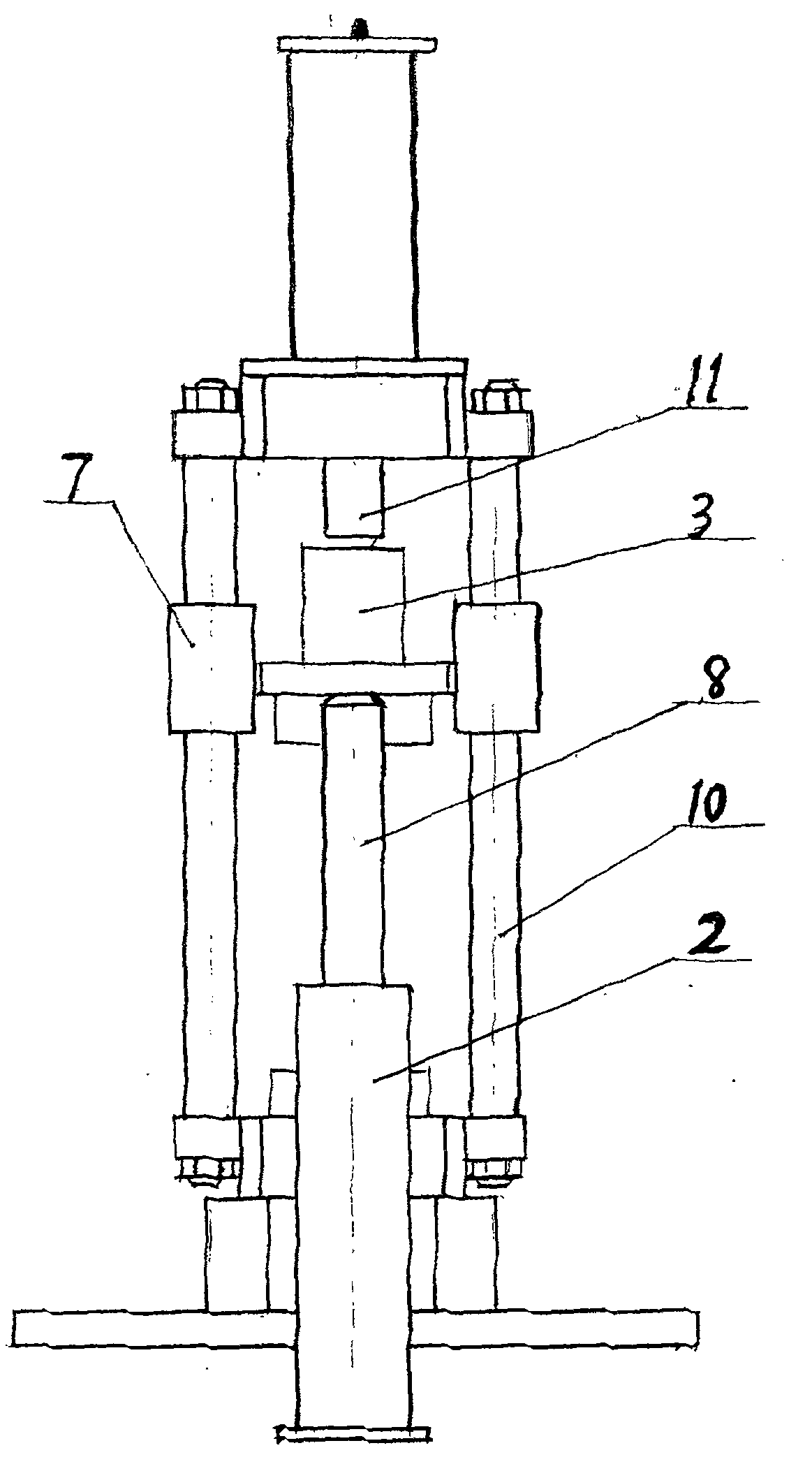
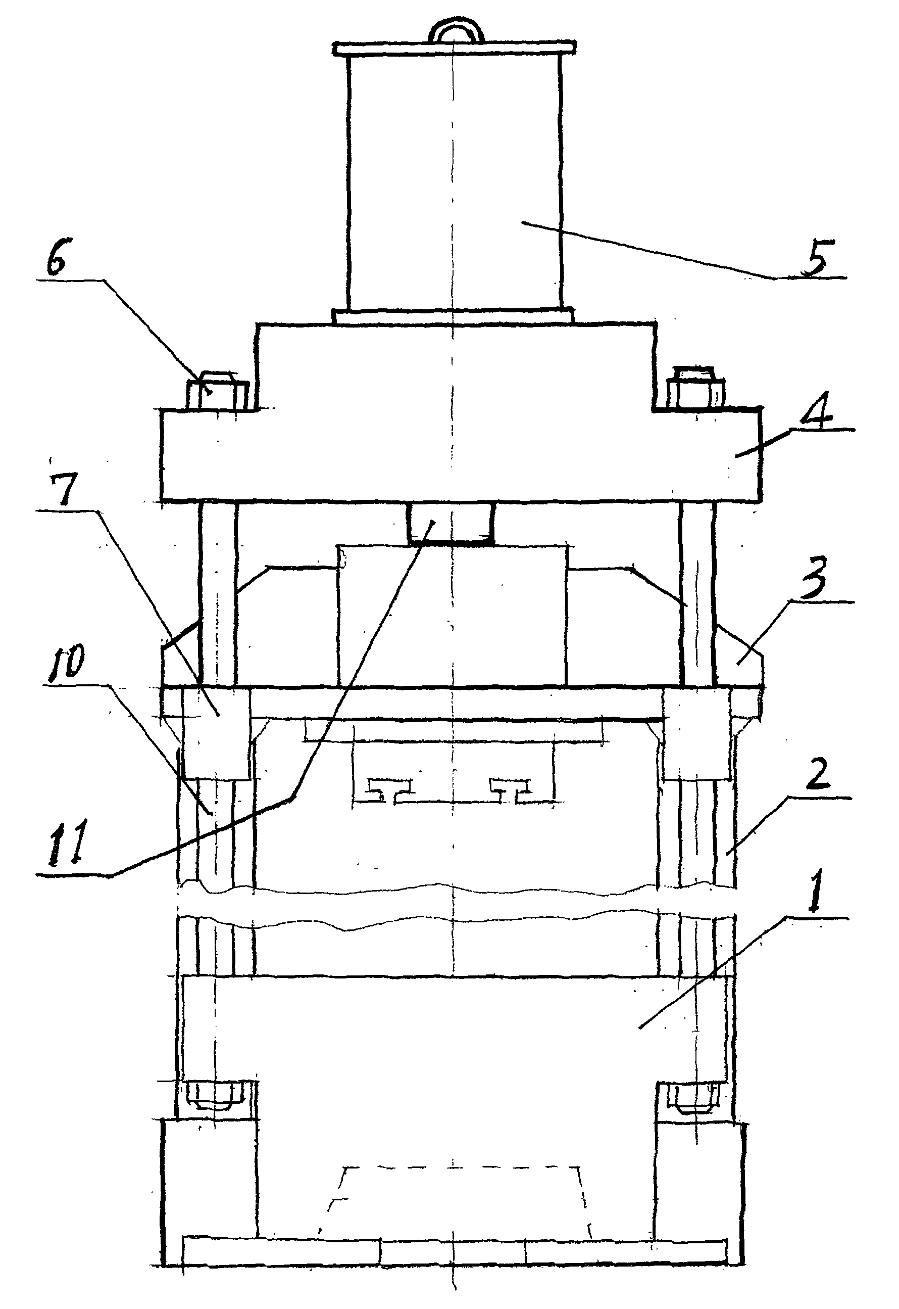
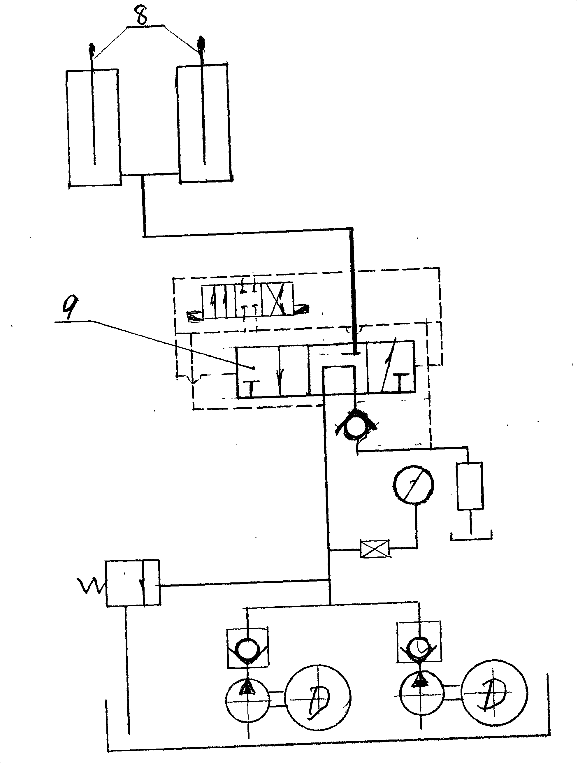
[0012] Pneumatic and hydraulic presses, such as figure 1 , 2 , shown in 3, nut 6 is arranged at both ends of four columns 10, bottom beam 1 and top beam 4 are fixed on the bottom and the top of four columns 10 with nut 6 respectively, form integral frame. Bottom beam 1 and top beam 4 are respectively located at the bottom and top of the frame, nitrogen compression cylinder 5 is installed on the top beam 1, two one-way hydraulic cylinders 2 are respectively installed on both sides of frame bottom beam 1, two single The cylinder piston rod 8 of the hydraulic cylinder 2 is pushed against the two ends of the punch 3 below. The punch 3 is provided with four guide sleeves 7, and the guide sleeves 7 are respectively sleeved on the four columns 10, and can slide up and down along the four top beams 4. The nitrogen compression cylinder piston rod 11 is connec...


PUM


Abstract

The invention relates to an air compression/hydraulic punching machine. An integral rack consists of a bottom beam, a top beam and four upright posts of a machine body, wherein the bottom beam and the top beam are respectively arranged at the bottom part and the top part of the rack, the four upright posts are supported between the bottom beam and the top beam, a nitrogen compression cylinder is arranged at the upper part of the top beam, a punch is provided with four guide sleeves, the four guide sleeves are respectively sleeved on the four upright posts, and the four guide sleeves can slide on the four upright posts. A piston and a piston rod of the nitrogen compression cylinder are connected to the upper surface of the punch, two one-way hydraulic oil cylinders are arranged on the bottom beam of the machine body, and piston rods of the two one-way hydraulic oil cylinders lean against the punch. Hydraulic oil supplied by a hydraulic station can get in and out of the two one-way hydraulic oil cylinders in the same ratio and the same pressure through a three-position three-way electro-hydraulic directional valve, and punching movements of ascending and descending of the punch can be completed by the air compression/hydraulic punching machine through piston motions of the two one-way hydraulic oil cylinders and the nitrogen compression cylinder. An electrical appliance control system of the air compression/hydraulic punching machine is provided with two travel switches. The air compression/hydraulic punching machine disclosed by the invention is simple, convenient and flexible in operation method, is small in mechanical noise and is a comparatively ideal punching device.

Description

technical field [0001] The patent of the present invention relates to the technical field of forging equipment, specifically a steam and hydraulic press. Background technique [0002] The used lathe of present domestic machinery industry all is to carry out stamping work with big and heavy flywheel to drive crankshaft connecting rod mechanism. This form of punch press has many consumables, is heavy, and has a lot of mechanical noise. Once overloaded during work, it is easy to cause the bed to crack and make the punch press scrapped. Contents of the invention [0003] The purpose of the present invention is to provide a new type of forging equipment-pneumatic and hydraulic presses. The present invention changes the transmission form of the flywheel and the crankshaft connecting rod mechanism of the original punching machine into an air pressure and hydraulic transmission form. Pneumatic and hydraulic presses have less consumables, simple manufacturing process and low man...

Claims


Application Information

Patent Timeline
Patent Type & Authority Applications(China)
IPC IPC(8): B30B1/38B30B1/32B21J9/18
Inventor 穆以东屈鹏袁真德冯德瀛
Owner LIAOCHENG UNIV
Why Eureka
Try Eureka