Washing production line after printing and dyeing

A production line, washing water technology, applied in textile and papermaking, liquid/gas/vapor textile processing, liquid/gas/vapor removal with squeeze rollers, etc. problems, to achieve low energy consumption, clean and environmentally friendly production, good dehydration and cleaning effects, and the effect of reducing labor intensity

Active Publication Date: 2014-02-05
JINJIANG CITY LONGSHENG KNITTING PRINTING & DYEING CO LTD
View PDF5 Cites 12 Cited by
  • Summary
  • Abstract
  • Description
  • Claims
  • Application Information

AI Technical Summary

Problems solved by technology

Compared with other printing and dyeing processes, the processing steps of washing water after printing are cumbersome and consume more water and heat. With the shortage of energy, the increase of prices, and the needs of environmental protection, the disadvantages of traditional washing devices are more obvious. Change this status quo imperative
[0003] At present, the traditional washing production line after printing and dyeing is a straight line with a length of about 40 meters. The laborers have to go back and forth for inspection every 5 to 10 minutes, which is extremely labor intensive; There are a number of washing units and water squeezing devices between the tanks. The cloth feeding device and the cloth outlet device are respectively arranged at the head and tail of the production line. The water squeezing device between the tanks is located between the washing water units and is used to transfer The rope-shaped cloth is squeezed, and its washing unit has a washing tank; the lower part of the washing tank is provided with compartments through the partition, and the upper part of the washing tank is equipped with a cloth rolling ro

Method used


Image

  • Washing production line after printing and dyeing
  • Washing production line after printing and dyeing
  • Washing production line after printing and dyeing

Examples


Example Embodiment

[0020] The preferred embodiments of the present invention will be described in detail below in conjunction with the accompanying drawings.

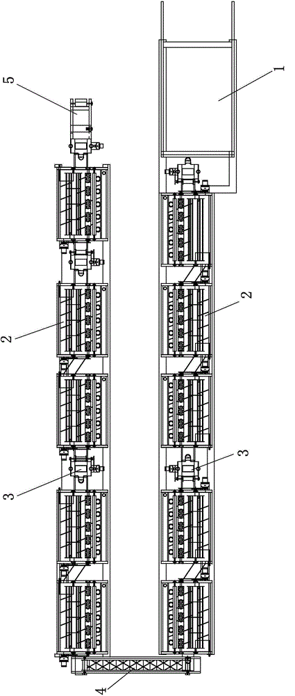
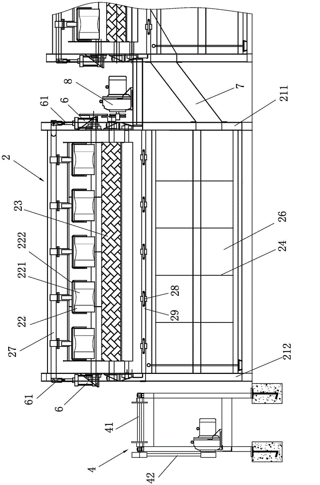
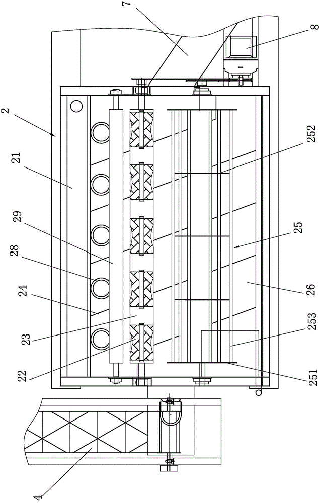
[0021] Such as Figure 1 to Figure 5 As shown, a post-printing and dyeing washing production line includes a washing unit 2 arranged on the production line, a water squeezing device 3 between the boxes, and a cloth feeding device 1 and a cloth discharging device 5 respectively arranged at the beginning and end of the production line. The production line is arranged in a folded back " U" shape, one end of the two parallel longitudinal production lines is connected by a horizontal turning guide belt 4, which is installed on the drum 41, and the drum 41 is driven by the transmission device 42. The turning guide belt 4 connects the upstream washing unit 2 The discharge port is connected with the feed port of the washing water unit 2 on the downstream side, and a water squeezing device 3 is provided between some washing water units 2. The other ...


PUM


Abstract

The invention provides a washing production line after printing and dyeing. The washing production line comprises wash water units, inter-box wringing devices as well as a fabric feeding device and a fabric discharge device which are distributed at the head and the tail of the production line respectively. The washing production line is characterized in that the production line is distributed in a U shape; and each wash water unit comprises a wash water groove, upper wringing rollers, lower wringing rollers, flow partition boards and cropping rollers, the upper wringing rollers and the lower wringing rollers are vertically opposite and located above isolation grooves, and are arranged in the length direction of the production line, the cropping rollers are located on the near sides of the lower wringing rollers, and each upper wringing roller is located above the corresponding isolation groove and can perform wringing movement of approaching and leaving the lower wringing rollers. With the adoption of the washing production line after printing and dyeing, the labor intensity of an operator can be reduced, a fabric is separated from a washing liquid after every time of cleaning and subjected to repeated wringing piece by piece, the cleaning gradient of the washing liquid is changed, and efficient, high-quality and environment-friendly production with low water and energy consumption is realized.

Description

technical field [0001] The invention relates to printing and dyeing equipment, in particular to a washing production line for washing after printing and dyeing. Background technique [0002] The printing and dyeing industry is an industry with a large amount of industrial water consumption and polluted wastewater discharge. It is one of the five key water engineering departments and a large sewage discharger after the power generation industry. my country is also one of the countries with serious water shortage and water pollution. Therefore, implementing clean production, saving water and reducing pollution is the only way for the sustainable development of my country's printing and dyeing industry. Compared with other printing and dyeing processes, the processing steps of washing water after printing are cumbersome and consume more water and heat. With the shortage of energy, the increase of prices, and the needs of environmental protection, the disadvantages of traditiona...

Claims


Application Information

Patent Timeline
IPC IPC(8): D06B23/20D06B3/10D06B15/02D06B23/04D06B1/02
Inventor 李满武
Owner JINJIANG CITY LONGSHENG KNITTING PRINTING & DYEING CO LTD
Why Eureka
Try Eureka