

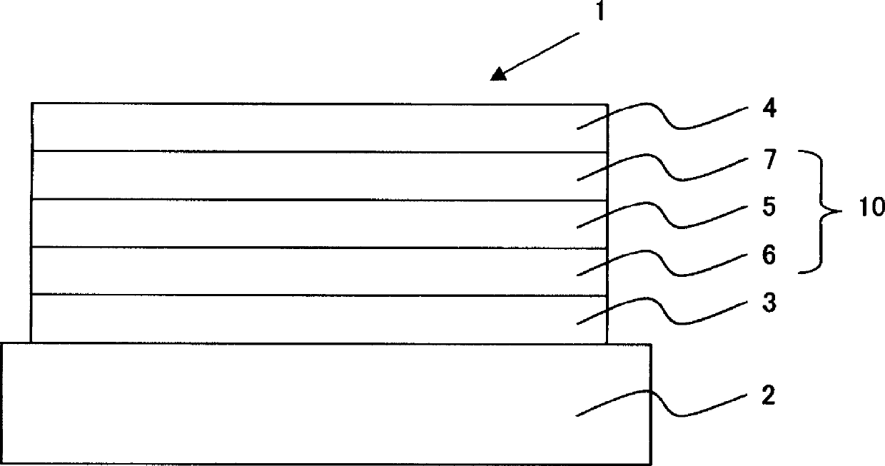
Organic electroluminescent element
A kind of electroluminescent element, electroluminescent technology
- Summary
- Abstract
- Description
- Claims
- Application Information
AI Technical Summary
Problems solved by technology
Method used
Image


Examples
Embodiment
[0386] The following examples illustrate the present invention in detail, and the present invention is not limited by them.
Synthetic example 1
[0388] (Synthesis of Intermediate 1)
[0389] [chemical formula 84]
[0390]
[0391] Under argon flow, 2-nitro-1,4-dibromobenzene (11.2g, 40mmol), phenylboronic acid (4.9g, 40mmol), and tetrakis(triphenylphosphine)palladium (1.39g, 1.2mmol) were added in sequence , toluene (120 mL), 2M aqueous sodium carbonate solution (60 mL) and heated to reflux for 8 hours.
[0392] After cooling the reaction solution to room temperature, the organic layer was separated, and the organic solvent was distilled off under reduced pressure. The obtained residue was purified by silica gel chromatography to obtain Intermediate 1 (6.6 g, yield 59%). It was identified as intermediate 1 by FD-MS (field desorption mass spectrometry) analysis.
[0393] (Synthesis of Intermediate 2)
[0394] [chemical formula 85]
[0395]
[0396] Under argon flow, Intermediate 1 (6.6g, 23.7mmol), triphenylphosphine (15.6g, 59.3mmol), o-dichlorobenzene (24mL) were sequentially added and heated at 180°C for 8...
Embodiment 1
[0418] (Production of organic EL elements)
[0419] A 25 mm x 75 mm x 1.1 mm glass substrate with an ITO transparent electrode (manufactured by Geomatics) was subjected to ultrasonic cleaning in isopropanol for 5 minutes, and then to UV (ultraviolet) ozone cleaning for 30 minutes.
[0420] Assemble the washed glass substrate with transparent electrode lines on the substrate holder of the vacuum evaporation device, and first vapor-deposit the following electron-accepting Compound (A), A film with a film thickness of 5 nm was formed. On this film A, the following aromatic amine derivative (X1) was vapor-deposited as a first hole transport material to form a first hole transport layer with a film thickness of 120 nm. After forming the first hole transport layer, the following carbazole derivative (H1) was vapor-deposited as a second hole transport material to form a second hole transport layer with a film thickness of 47 nm.
[0421]Compound (B1) as a host for phosphorescence a...
PUM
| Property | Measurement | Unit |
|---|---|---|
| thickness | aaaaa | aaaaa |
| thickness | aaaaa | aaaaa |
| thickness | aaaaa | aaaaa |
Abstract
Description
Claims
Application Information