
Diaphragm laser cutting device

A laser cutting and diaphragm technology, applied in auxiliary devices, laser welding equipment, welding/cutting auxiliary equipment, etc., can solve the problems of surface tension damage of quality diaphragm, reduce product qualification rate, waste copper plate waste, etc., to achieve separation Convenience, improve production efficiency, reduce friction effect

Active Publication Date: 2016-01-13
JIANGSU HUAFENG ELECTRONICS
View PDF6 Cites 0 Cited by
  • Summary
  • Abstract
  • Description
  • Claims
  • Application Information

AI Technical Summary

Problems solved by technology

After flushing, there is a lot of waste of copper plate waste, which leads to extremely high production costs, and the cost of a single unit is nearly doubled
In terms of quality, the surface tension of the diaphragm of the product will be greatly damaged, which will reduce the qualified rate of the product

Method used


Image

  • Diaphragm laser cutting device
  • Diaphragm laser cutting device
  • Diaphragm laser cutting device

Examples


Embodiment Construction

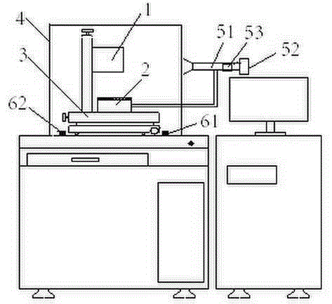
[0024] The specific implementation manners of the present invention will be further described below in conjunction with the drawings and examples. The following examples are only used to illustrate the technical solution of the present invention more clearly, but not to limit the protection scope of the present invention.

[0025] The technical scheme of concrete implementation of the present invention is:

[0026] Such as figure 1 As shown, a diaphragm 8 laser cutting device includes a laser generator 1 for cutting out a diaphragm 9 monomer on the diaphragm 8, a positioning tool 2 for fixing the diaphragm 8, and a positioning tool for adjusting 2 a position adjustment mechanism 3 relative to the laser generator 1;

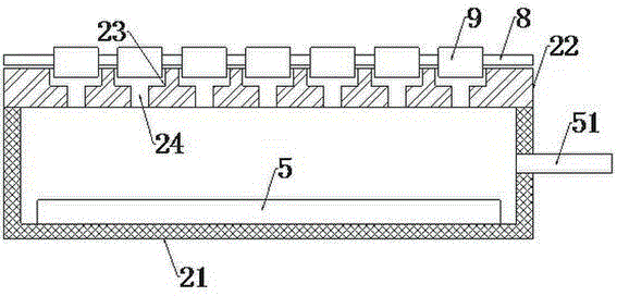
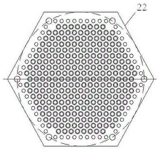
[0027] The positioning tool 2 includes a bin body 21 with an open top and a flat carrier plate 22 that closes the top opening of the bin body 21; Dimple 23, the bottom surface of the dimple 23 is provided with a through hole 24 connected to the lower surface of...


PUM


Abstract

The invention discloses a diaphragm laser cutting device. The diaphragm laser cutting device comprises a laser generator, a locating tool and a position adjusting mechanism, wherein the laser generator is used for enabling diaphragm ring single bodies to be cut out on a diaphragm, the locating tool is used for fixing the diaphragm, and the position adjusting mechanism is used for adjusting the relative position of the locating tool and the laser generator. According to the diaphragm laser cutting device, mass cutting can be carried out on vibrating diaphragms of electret microphones by using laser equipment, and the cutting precision of the vibrating diaphragms is high.

Description

technical field [0001] The invention relates to a diaphragm laser cutting device, in particular to a device for automatically cutting the vibrating membrane of an electret microphone in batches by using laser equipment. Background technique [0002] There are several membrane rings (diaphragms) on the diaphragm of the electret microphone, and each membrane ring needs to be cut off accurately. There are two cutting processes for the production of the diaphragm of the current electret microphone: [0003] One technique is to manually remove the annulus from a large sheet, rotating them piece by piece with a compass and a razor blade. The worker puts the side with the film down and the side with the ring up, and lays it flat, then puts it into the inner side of the film ring with a fixed head, controls the compass to rotate a circle with the blade to cut off a single film ring, and then cuts off a single film ring according to And so on, cutting one by one. This method is lab...

Claims


Application Information

Patent Timeline
Patent Type & Authority Patents(China)
IPC IPC(8): B23K26/38B23K26/16
CPCB23K26/16B23K26/38B23K26/702B23K37/0408
Inventor 张伙根
Owner JIANGSU HUAFENG ELECTRONICS
Learn More